


Operating Instructions
1780R-Series Operator’s Manual
3–51
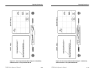
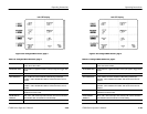
3. <READOUT INTENSITY> will be circled, and a test readout
will be displayed. Use the large knob to adjust intensity. (The
front-panel INTENSITY control adjusts signal intensity only.
Readout intensity must be adjusted through the Calibration
menu.)
4. Touch <TRACE ROTATION> to obtain a test axis, then use the
large knob to adjust trace rotation.
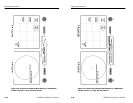
5. Touch <CAL OSC> until <ON> is outlined. While the cal
oscillator is on, the V axis switcher is enabled and 75% bars are
selected (with setup for NTSC).
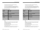
a. Touch <GAIN CAL>. The large knob will now adjust
vectorscope gain. Use the large knob to make the circle
match the compass rose.
b. Exit Calibrate menu.
Perform Step 6 for 1780R (NTSC ) only.
6. Apply a 75% color bar signal with no setup to a 1780R input
channel and select that channel for display.
a. Push the front-panel CONFIGURE button to enter the
Configure menu. Touch the <PAGE> area of the screen
until <2> is outlined.
b. Touch <SETUP> until <NO> is outlined.
c. Touch <BARS> until <75%> is outlined.
d. Push the front-panel PHASE button to assign the large
knob function to phase shift. Adjust the large knob to
properly align the burst and vectors on the graticule.
e. Push the front-panel CALIBRATE button to enter the
Calibration menu, then push the button under the left
CRT.
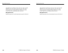
f. Touch <GAIN CAL>. The large knob will now adjust
vectorscope gain. Use the large knob to set the color bar
vectors to fall on the boxes.
g. Exit Calibrate menu.
Operating Instructions
1780R-Series Operator’s Manual
3–51
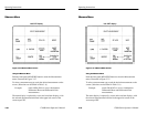
3. <READOUT INTENSITY> will be circled, and a test readout
will be displayed. Use the large knob to adjust intensity. (The
front-panel INTENSITY control adjusts signal intensity only.
Readout intensity must be adjusted through the Calibration
menu.)
4. Touch <TRACE ROTATION> to obtain a test axis, then use the
large knob to adjust trace rotation.
5. Touch <CAL OSC> until <ON> is outlined. While the cal
oscillator is on, the V axis switcher is enabled and 75% bars are
selected (with setup for NTSC).
a. Touch <GAIN CAL>. The large knob will now adjust
vectorscope gain. Use the large knob to make the circle
match the compass rose.
b. Exit Calibrate menu.
Perform Step 6 for 1780R (NTSC ) only.
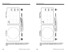
6. Apply a 75% color bar signal with no setup to a 1780R input
channel and select that channel for display.
a. Push the front-panel CONFIGURE button to enter the
Configure menu. Touch the <PAGE> area of the screen
until <2> is outlined.
b. Touch <SETUP> until <NO> is outlined.
c. Touch <BARS> until <75%> is outlined.
d. Push the front-panel PHASE button to assign the large
knob function to phase shift. Adjust the large knob to
properly align the burst and vectors on the graticule.
e. Push the front-panel CALIBRATE button to enter the
Calibration menu, then push the button under the left
CRT.
f. Touch <GAIN CAL>. The large knob will now adjust
vectorscope gain. Use the large knob to set the color bar
vectors to fall on the boxes.
g. Exit Calibrate menu.