


Operating Instructions
3–30
1780R-Series Operator’s Manual
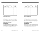
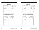
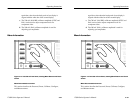
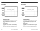
2. Use the large knob to align a horizontal reference point (usually
the sync tip) of one display with the white bar of the second
display.
3. Push the REF SET button and obtain a CAL readout of 0.00 dB
and 100.0%.
4. Relative burst amplitude is measured in the same manner as
absolute (see step 3 of the preceding procedure). The CAL
readout will display the burst amplitude in dB and % of the total
signal amplitude.
5. The relative amplitude of any portion of the signal can be
measured in the same manner: use the large knob to align the
bottom of the desired feature with the top of the second
appearance of that same feature. The relative readouts are
provided in dB and percent (%) of total signal amplitude.
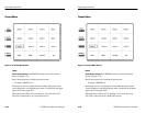
Using FIX. The 1780R-Series large knob has no effect in the <FIX>
mode.
This mode is used to compare the amplitude of the incoming video
signal to several internally calibrated amplitudes.
1. Enter the WFM+CAL mode. Use the touch screen to select
<FIX>. Select 2 Line and Flat filter. Apply a color bar signal to
the 1780R-Series.
2. For NTSC, if an IRE readout is desired, be sure that <IRE> is
selected on page 1 of the Configure menu.
3. Select the calibrator signal amplitude on page 1 of the Calibrate
menu.
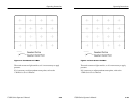
4. Adjust the amplitude of the incoming video signal until the CAL
readout reflects the exact amplitude selected in step 3.
a. When using the calibrator setting of 1000 mV (140.0
IRE), the CAL readout should equal that value when the
sync tip of one display is aligned with the white bar of the
second display.
b. When using the calibrator setting of 714 mV (100.0 IRE)
for NTSC, or 700 mV for PAL, the CAL readout should
Operating Instructions
3–30
1780R-Series Operator’s Manual
2. Use the large knob to align a horizontal reference point (usually
the sync tip) of one display with the white bar of the second
display.
3. Push the REF SET button and obtain a CAL readout of 0.00 dB
and 100.0%.
4. Relative burst amplitude is measured in the same manner as
absolute (see step 3 of the preceding procedure). The CAL
readout will display the burst amplitude in dB and % of the total
signal amplitude.
5. The relative amplitude of any portion of the signal can be
measured in the same manner: use the large knob to align the
bottom of the desired feature with the top of the second
appearance of that same feature. The relative readouts are
provided in dB and percent (%) of total signal amplitude.
Using FIX. The 1780R-Series large knob has no effect in the <FIX>
mode.
This mode is used to compare the amplitude of the incoming video
signal to several internally calibrated amplitudes.
1. Enter the WFM+CAL mode. Use the touch screen to select
<FIX>. Select 2 Line and Flat filter. Apply a color bar signal to
the 1780R-Series.
2. For NTSC, if an IRE readout is desired, be sure that <IRE> is
selected on page 1 of the Configure menu.
3. Select the calibrator signal amplitude on page 1 of the Calibrate
menu.
4. Adjust the amplitude of the incoming video signal until the CAL
readout reflects the exact amplitude selected in step 3.
a. When using the calibrator setting of 1000 mV (140.0
IRE), the CAL readout should equal that value when the
sync tip of one display is aligned with the white bar of the
second display.
b. When using the calibrator setting of 714 mV (100.0 IRE)
for NTSC, or 700 mV for PAL, the CAL readout should