Operating Instructions
3–8
1780R-Series Operator’s Manual
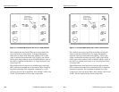
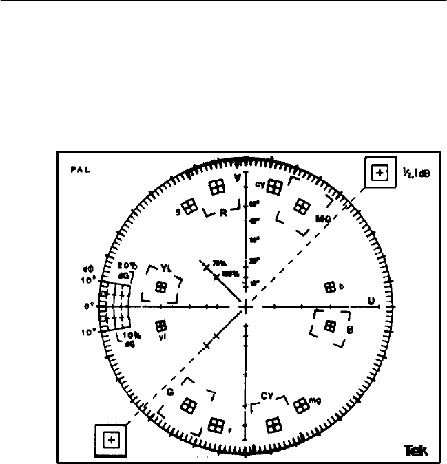
amplitude centered around 100% standard amplitude. The dimen-
sions of the smaller inner target represent ±3_ and ±5% of chromi-
nance amplitude. Note that the chrominance vectors associated with
the –V burst are terminated in the smaller targets only.
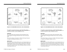
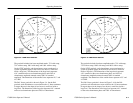
Figure 3–4: 1781R Vector Graticule
On the NTSC graticule, the small marks at intervals along the I and
Q axes denote the amplitudes of the chrominance components. On
the PAL graticule, the small marks at intervals along the U and V
axes denote the amplitudes of the U and V chrominance components.
The horizontal and vertical axes of the vector graticule contain
markings for checking Vector mode bandwidth. A subcarrier
frequency sine wave whose amplitude places it on the outer compass
rose is used as a reference. When the frequency is changed, the
diameter of the circle should reduce. At a point equal to 70% of full


