


Operating Instructions
1780R-Series Operator’s Manual
3–29
When operating in the <VAR> mode, software versions 1.11 & Up
provide a choice of absolute or relative readouts. When <ABS> is
selected, the readout appears in IRE or mV. (For an IRE readout,
<IRE> must be selected on page 2 of the Configure menu.) When
<REL> is selected, the readout is given in both dB and percentage
(%) values, relative to a reference that is selected by pushing the
REF SET button. (Software versions below 1.11 provide a relative
readout only.)
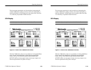
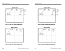
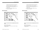
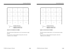
Making Measurements Using VAR and ABS. This mode provides accurate
amplitude measurements in IRE or mV values. An example of the
readout is shown in Figure 3–13 (calibrator signal not shown).
1. Enter the WFM+CAL mode. Use the touch screen to select
<VAR> and <ABS>. Select Two Line sweep and Flat filter.
Apply a color bar signal to the 1780R-Series.
2. To measure the signal amplitude (sync tip to white bar), locate
the sync tip on the topmost of the two displays. Use the large
knob to vertically align the bottom of that sync tip with the white
bar of the bottom display. The CAL readout now displays sync
tip to white bar amplitude. X5 Gain can be used if desired.
3. To measure burst amplitude, locate the burst on the top display.
Use the large knob to vertically align the bottom of that burst
with the top of the lower display’s burst packet. The CAL readout
now displays burst amplitude.
4. Any feature of the waveform can be measured in the same
manner; use the large knob to align the bottom of the desired
feature with the top of the second appearance of that same
feature. This provides a readout of the voltage offset between the
two displays.
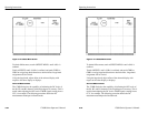
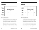
Making Measurements Using VAR and REL. This mode provides relative
measurements in dB and percent. An example of the readout is
shown in Figure 3–14 (calibrator signal not shown).
1. Enter the WFM+CAL mode. Use the touch screen to select
<VAR> and <REL>. Select Two Line sweep and Flat filter.
Apply a color bar signal to the 1780R-Series.
Operating Instructions
1780R-Series Operator’s Manual
3–29
When operating in the <VAR> mode, software versions 1.11 & Up
provide a choice of absolute or relative readouts. When <ABS> is
selected, the readout appears in IRE or mV. (For an IRE readout,
<IRE> must be selected on page 2 of the Configure menu.) When
<REL> is selected, the readout is given in both dB and percentage
(%) values, relative to a reference that is selected by pushing the
REF SET button. (Software versions below 1.11 provide a relative
readout only.)
Making Measurements Using VAR and ABS. This mode provides accurate
amplitude measurements in IRE or mV values. An example of the
readout is shown in Figure 3–13 (calibrator signal not shown).
1. Enter the WFM+CAL mode. Use the touch screen to select
<VAR> and <ABS>. Select Two Line sweep and Flat filter.
Apply a color bar signal to the 1780R-Series.
2. To measure the signal amplitude (sync tip to white bar), locate
the sync tip on the topmost of the two displays. Use the large
knob to vertically align the bottom of that sync tip with the white
bar of the bottom display. The CAL readout now displays sync
tip to white bar amplitude. X5 Gain can be used if desired.
3. To measure burst amplitude, locate the burst on the top display.
Use the large knob to vertically align the bottom of that burst
with the top of the lower display’s burst packet. The CAL readout
now displays burst amplitude.
4. Any feature of the waveform can be measured in the same
manner; use the large knob to align the bottom of the desired
feature with the top of the second appearance of that same
feature. This provides a readout of the voltage offset between the
two displays.
Making Measurements Using VAR and REL. This mode provides relative
measurements in dB and percent. An example of the readout is
shown in Figure 3–14 (calibrator signal not shown).
1. Enter the WFM+CAL mode. Use the touch screen to select
<VAR> and <REL>. Select Two Line sweep and Flat filter.
Apply a color bar signal to the 1780R-Series.