


Operating Instructions
1780R-Series Operator’s Manual
3–21
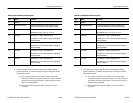
The data stream transmitted to and from the host (representing the
current 1780R-Series settings) consists of 512 bytes, followed by a
one-byte checksum. All data bytes are in the range of Hex 20 to Hex
7F, so that they are printable ASCII characters.
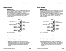
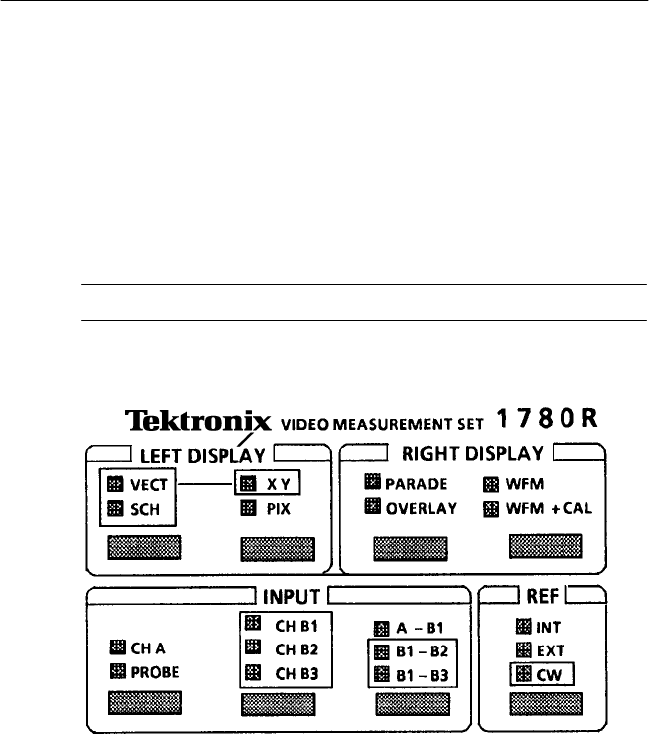
SCH Display
NOTE. Switch function is further described in Section 2.
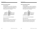
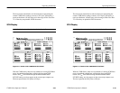
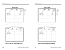
Figure 3–11: Portion of the 1780R-Series Front Panel
With the 1780R-Series, there are two methods of viewing SCH Phase
errors; the method outlined here, utilizing the front-panel SCH
button, and F
SC
Time Marks through the Measurement Menu.
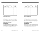
INT REF setting: two dots appear on the vectorscope compass rose.
The dots represent the 50% points of H Sync.
Operating Instructions
1780R-Series Operator’s Manual
3–21
The data stream transmitted to and from the host (representing the
current 1780R-Series settings) consists of 512 bytes, followed by a
one-byte checksum. All data bytes are in the range of Hex 20 to Hex
7F, so that they are printable ASCII characters.
SCH Display
NOTE. Switch function is further described in Section 2.
Figure 3–11: Portion of the 1780R-Series Front Panel
With the 1780R-Series, there are two methods of viewing SCH Phase
errors; the method outlined here, utilizing the front-panel SCH
button, and F
SC
Time Marks through the Measurement Menu.
INT REF setting: two dots appear on the vectorscope compass rose.
The dots represent the 50% points of H Sync.