


Operating Instructions
3–18
1780R-Series Operator’s Manual
Serial Communications Interface
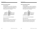
Serial Interface Connector
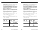
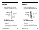
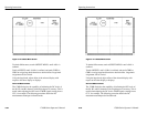
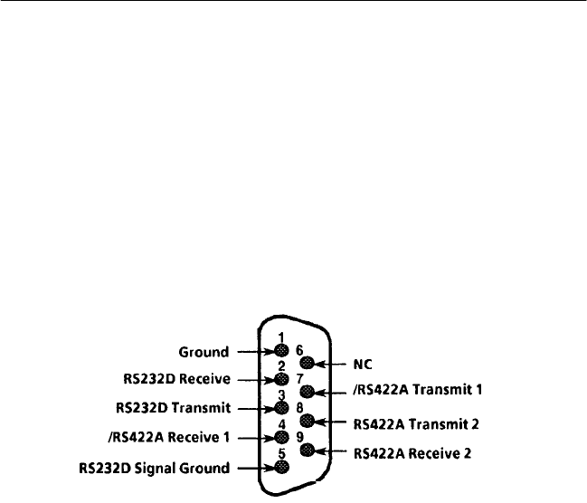
The rear-panel SERIAL interface connector is a 9-pin, sub-minia-
ture, D-type connector. It is used as an RS422A or RS232D interface
to the 1780R-Series microcontroller. Drivers for both interfaces are
resident. RS422A is a balanced voltage digital interface, and
RS232D is a serial binary data interchange. Figure 3–9 shows the
rear-panel SERIAL connector pin assignments.
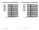
Figure 3–9: Serial Interface Connector Pin Assignments
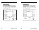
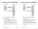
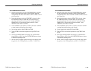
Building a Wiring Converter
Wiring converters can be built to connect the 1780R-Series 9-pin
SERIAL port with another 9-pin connector or with a 25-pin
connector. The 25-pin converter uses a 9-pin male connector
(Tektronix P/N 131-1007-00) and a 25-pin female connector
(Tektronix P/N 131-0971-00), as illustrated in Figure 3–10.
Operating Instructions
3–18
1780R-Series Operator’s Manual
Serial Communications Interface
Serial Interface Connector
The rear-panel SERIAL interface connector is a 9-pin, sub-minia-
ture, D-type connector. It is used as an RS422A or RS232D interface
to the 1780R-Series microcontroller. Drivers for both interfaces are
resident. RS422A is a balanced voltage digital interface, and
RS232D is a serial binary data interchange. Figure 3–9 shows the
rear-panel SERIAL connector pin assignments.
Figure 3–9: Serial Interface Connector Pin Assignments
Building a Wiring Converter
Wiring converters can be built to connect the 1780R-Series 9-pin
SERIAL port with another 9-pin connector or with a 25-pin
connector. The 25-pin converter uses a 9-pin male connector
(Tektronix P/N 131-1007-00) and a 25-pin female connector
(Tektronix P/N 131-0971-00), as illustrated in Figure 3–10.