


Operating Instructions
3–2
1780R-Series Operator’s Manual
For software versions 1.13 and up, installed in instruments SN
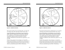
B020100 and up: The Timing Cursor dots are positioned on the
Voltage Cursors while in Line Select mode, for ease in viewing the
Timing Cursors.
Voltage Cursors
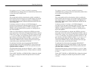
Push the VOLTAGE switch to enable the voltage cursors and obtain
a menu on the vectorscope CRT. Use this menu to choose cursors
that track together or are positioned separately, and to choose
between absolute and relative readout.
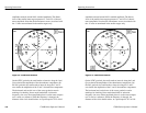
Cursor One appears as a dashed horizontal line, and Cursor Two as a
series of two short dashes on the waveform monitor display.
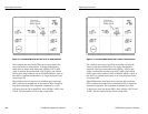
The large knob provides continuous adjustment of cursors. The < >
buttons provide adjustment in discrete steps of 0.1 IRE or 1mV
(depending on the Configure menu ABS UNITS selection).
To change the large knob assignment from one cursor to another,
touch the quadrant labeled <CURSOR 1 / CURSOR 2>. The current
assignment is outlined by a box.
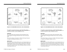
When <SEPARATE> is selected by touching the <SEPARATE /
TRACK> area of the screen, the cursors are moved one at a time
(currently selected cursor is outlined). When <TRACK> is selected,
both cursors move at once.
When <ABSOLUTE> is selected, the readout (in IRE or mV)
indicates the voltage difference between the two cursors. The mV /
IRE selection is made through page 2 of the Configure menu. The
Configure menu instructions appear later in this section.
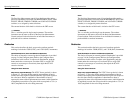
REFERENCE SET has no effect in Absolute mode.
When <RELATIVE> is selected, the readout is shown in percent and
dB, relative to the value when REFERENCE SET was last pushed.
REFERENCE SET resets the relative value to 100.0% (0 dB).
If vertical gain is employed, the cursor interval is magnified
correspondingly. Voltage difference between Cursor One and Cursor
Two can be determined, even though they may not both be on screen
at the same time.
Operating Instructions
3–2
1780R-Series Operator’s Manual
For software versions 1.13 and up, installed in instruments SN
B020100 and up: The Timing Cursor dots are positioned on the
Voltage Cursors while in Line Select mode, for ease in viewing the
Timing Cursors.
Voltage Cursors
Push the VOLTAGE switch to enable the voltage cursors and obtain
a menu on the vectorscope CRT. Use this menu to choose cursors
that track together or are positioned separately, and to choose
between absolute and relative readout.
Cursor One appears as a dashed horizontal line, and Cursor Two as a
series of two short dashes on the waveform monitor display.
The large knob provides continuous adjustment of cursors. The < >
buttons provide adjustment in discrete steps of 0.1 IRE or 1mV
(depending on the Configure menu ABS UNITS selection).
To change the large knob assignment from one cursor to another,
touch the quadrant labeled <CURSOR 1 / CURSOR 2>. The current
assignment is outlined by a box.
When <SEPARATE> is selected by touching the <SEPARATE /
TRACK> area of the screen, the cursors are moved one at a time
(currently selected cursor is outlined). When <TRACK> is selected,
both cursors move at once.
When <ABSOLUTE> is selected, the readout (in IRE or mV)
indicates the voltage difference between the two cursors. The mV /
IRE selection is made through page 2 of the Configure menu. The
Configure menu instructions appear later in this section.
REFERENCE SET has no effect in Absolute mode.
When <RELATIVE> is selected, the readout is shown in percent and
dB, relative to the value when REFERENCE SET was last pushed.
REFERENCE SET resets the relative value to 100.0% (0 dB).
If vertical gain is employed, the cursor interval is magnified
correspondingly. Voltage difference between Cursor One and Cursor
Two can be determined, even though they may not both be on screen
at the same time.