


Operating Instructions
1780R-Series Operator’s Manual
3–15
Remote Operation
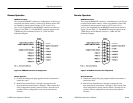
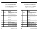
REMOTE Connector
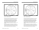
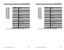
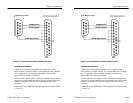
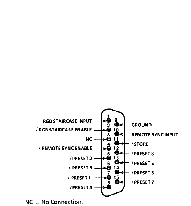
The rear-panel REMOTE connector is a subminiature 15-pin D-type
receptacle with female contacts. All the active Remote control lines
are enabled by remote ground closures or TTL levels (0 V to
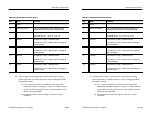
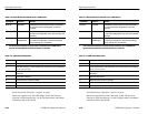
+0.8 V). Pin assignments for the REMOTE connector are shown in
Figure 3–8 and Table 3–2. The REMOTE connector appears in the
1780R-Series Service Manual, Section 11, UART and A/D
Schematic Diagram.
Figure 3–8: REMOTE Connector Pin Assignments
Remote Operation
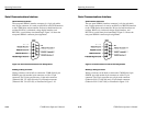
1. Connect the mating male plug supplied with the instrument to a
remote-box cable.
2. Remote lines named Presets 1 through 8 correspond to the
front-panel Preset menu Presets 1 through 8. These remote lines
allow configurations already stored at Presets 1 through 8 to be
recalled, and new configurations to be stored at those preset
locations.
Operating Instructions
1780R-Series Operator’s Manual
3–15
Remote Operation
REMOTE Connector
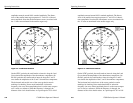
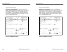
The rear-panel REMOTE connector is a subminiature 15-pin D-type
receptacle with female contacts. All the active Remote control lines
are enabled by remote ground closures or TTL levels (0 V to
+0.8 V). Pin assignments for the REMOTE connector are shown in
Figure 3–8 and Table 3–2. The REMOTE connector appears in the
1780R-Series Service Manual, Section 11, UART and A/D
Schematic Diagram.
Figure 3–8: REMOTE Connector Pin Assignments
Remote Operation
1. Connect the mating male plug supplied with the instrument to a
remote-box cable.
2. Remote lines named Presets 1 through 8 correspond to the
front-panel Preset menu Presets 1 through 8. These remote lines
allow configurations already stored at Presets 1 through 8 to be
recalled, and new configurations to be stored at those preset
locations.