


Connectors, Controls, Indicators
1780R-Series Operator’s Manual
2–15
NOTE. The three INPUT switches are companion switches. Refer to
the preceding Companion Switch Example.
Input
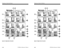
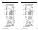
39. A–B1 / B1–B2 / B1–B3. This switch selects from the following
inputs for display: CH A minus CH B1, CH B1 minus CH B2, or
CH B1 minus CH B3. Push and hold this switch to select CH B1
minus CH B2 and CH B1 minus CH B3 together (Bowtie).
Instrument will be forced to 2-Line Parade operation.
40. CH B1 / CH B2 / CH B3. In WFM mode, push and release this
switch to select the rear-panel Channel B1, Channel B2, or
Channel B3 input for display on both CRTs. In Parade mode, all
three are forced on. In Overlay, it selects any two or all three
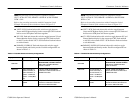
input channels on. Refer to Table 2–4 for an outline of possible
switch settings.
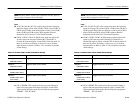
Table 2–4: Possible CH B1, CH B2, CH B3 Switch Settings
Display Possible Switch Settings
Overlay
T
oggl
es
be
tw
ee
n
2
chann
e
l
s
an
d
all
3
chann
e
l
s
on.
ONE LINE or FIELD
Waveform
T
oggl
es
to
se
l
e
ct any on
e
chann
e
l.
TWO LINE or FIELD
Parade
C
H B1,
C
H B
2
, an
d
C
H B
3
on tog
e
th
er
THREE LINE or FIELD
Waveform
T
oggl
es
to
se
l
e
ct any on
e
chann
e
l.
THREE LINE or FIELD
(Push & Hold)
41. CH A / PROBE. This switch selects the rear-panel Channel A
input or the front-panel Probe input for display on both CRTs.
Upon entering the Probe mode, the following message appears:
“PROBE– – 50V DC MAX.”
Connectors, Controls, Indicators
1780R-Series Operator’s Manual
2–15
NOTE. The three INPUT switches are companion switches. Refer to
the preceding Companion Switch Example.
Input
39. A–B1 / B1–B2 / B1–B3. This switch selects from the following
inputs for display: CH A minus CH B1, CH B1 minus CH B2, or
CH B1 minus CH B3. Push and hold this switch to select CH B1
minus CH B2 and CH B1 minus CH B3 together (Bowtie).
Instrument will be forced to 2-Line Parade operation.
40. CH B1 / CH B2 / CH B3. In WFM mode, push and release this
switch to select the rear-panel Channel B1, Channel B2, or
Channel B3 input for display on both CRTs. In Parade mode, all
three are forced on. In Overlay, it selects any two or all three
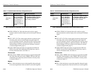
input channels on. Refer to Table 2–4 for an outline of possible
switch settings.
Table 2–4: Possible CH B1, CH B2, CH B3 Switch Settings
Display Possible Switch Settings
Overlay
T
oggl
es
be
tw
ee
n
2
chann
e
l
s
an
d
all
3
chann
e
l
s
on.
ONE LINE or FIELD
Waveform
T
oggl
es
to
se
l
e
ct any on
e
chann
e
l.
TWO LINE or FIELD
Parade
C
H B1,
C
H B
2
, an
d
C
H B
3
on tog
e
th
er
THREE LINE or FIELD
Waveform
T
oggl
es
to
se
l
e
ct any on
e
chann
e
l.
THREE LINE or FIELD
(Push & Hold)
41. CH A / PROBE. This switch selects the rear-panel Channel A
input or the front-panel Probe input for display on both CRTs.
Upon entering the Probe mode, the following message appears:
“PROBE– – 50V DC MAX.”