


Operating Instructions
3–22
1780R-Series Operator’s Manual
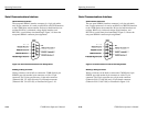
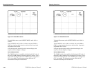
EXT REF setting: only one dot appears on the vectorscope compass
rose. This relative mode allows the comparison of the color framing
of two signals. The two signals are color framed when the sync dot is
within 90_ of the burst vector.
SCH Phase Measurement Procedure
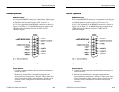
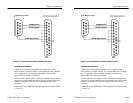
1. Select the SCH mode of operation by pushing the SCH / VECT
button, shown in Figure 3–11, until the SCH LED lights. Two
pushes may be required, depending on the previous condition.
2. Push the front-panel PHASE button.
3. Apply a signal to a 1780R-Series input channel and select that
channel for display.
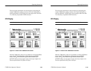
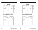
4. Use the large knob to align the burst vector with the 180_
graticule line (normal position). Push the REF SET button to
obtain a 0.00_ readout (vectorscope CRT).
5. Use the large knob to move the dot (or closest of the two dots in
INT REF mode) to the 180_ graticule line. Readout now shows
SCH Phase error.
6. Push the SCH and PHASE buttons again to exit the mode.
Operating Instructions
3–22
1780R-Series Operator’s Manual
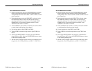
EXT REF setting: only one dot appears on the vectorscope compass
rose. This relative mode allows the comparison of the color framing
of two signals. The two signals are color framed when the sync dot is
within 90_ of the burst vector.
SCH Phase Measurement Procedure
1. Select the SCH mode of operation by pushing the SCH / VECT
button, shown in Figure 3–11, until the SCH LED lights. Two
pushes may be required, depending on the previous condition.
2. Push the front-panel PHASE button.
3. Apply a signal to a 1780R-Series input channel and select that
channel for display.
4. Use the large knob to align the burst vector with the 180_
graticule line (normal position). Push the REF SET button to
obtain a 0.00_ readout (vectorscope CRT).
5. Use the large knob to move the dot (or closest of the two dots in
INT REF mode) to the 180_ graticule line. Readout now shows
SCH Phase error.
6. Push the SCH and PHASE buttons again to exit the mode.