


Measurements
1780R-Series Operator’s Manual
4–37
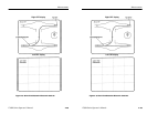
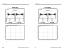
Making SCH Phase Measurements
The 1780R-Series offers two methods of measuring SCH phase
errors: The polar SCH display, and this F
SC
Time Marks (voltage-vs-
time) method. The F
SC
time marks display is more direct than the
polar display, and affords the operator more manual control, but may
provide a less precise measurement. To ensure an accurate
measurement, both methods can be used.
1. Adjust the waveform monitor controls for a high resolution
display of sync.
2. Adjust the large knob until one of the bright-up dots is at the 50%
point of the leading edge of sync on the waveform display.
3. Push the front-panel REFERENCE SET button. The phase
readout is now 0.00_.
4. Adjust the large knob until the dots are on the zero crossing (or
50% point) of burst on the waveform display.
5. The vectorscope CRT readout now gives SCH phase error in
degrees.
Voltage Cursors in F
SC
Time Marks Mode
While in Time Marks mode, push the front-panel VOLTAGE
CURSOR button. A voltage cursor menu appears on the right side of
the vectorscope CRT. Touch <ABSOLUTE / RELATIVE> or
<SEPARATE / TRACK> to toggle between those voltage cursor
functions. Refer to the section on Voltage Cursors in Section 3 of this
manual for more details.
Verifying Burst Position
The F
SC
time marks display can be used to verify that burst is
located 19 subcarrier cycles from the 50% point of the leading edge
of sync.
Position one of the dots on the 50% point of sync, and count the
number of dots between that dot and the dot on the zero crossing of
the first full cycle of burst.
Measurements
1780R-Series Operator’s Manual
4–37
Making SCH Phase Measurements
The 1780R-Series offers two methods of measuring SCH phase
errors: The polar SCH display, and this F
SC
Time Marks (voltage-vs-
time) method. The F
SC
time marks display is more direct than the
polar display, and affords the operator more manual control, but may
provide a less precise measurement. To ensure an accurate
measurement, both methods can be used.
1. Adjust the waveform monitor controls for a high resolution
display of sync.
2. Adjust the large knob until one of the bright-up dots is at the 50%
point of the leading edge of sync on the waveform display.
3. Push the front-panel REFERENCE SET button. The phase
readout is now 0.00_.
4. Adjust the large knob until the dots are on the zero crossing (or
50% point) of burst on the waveform display.
5. The vectorscope CRT readout now gives SCH phase error in
degrees.
Voltage Cursors in F
SC
Time Marks Mode
While in Time Marks mode, push the front-panel VOLTAGE
CURSOR button. A voltage cursor menu appears on the right side of
the vectorscope CRT. Touch <ABSOLUTE / RELATIVE> or
<SEPARATE / TRACK> to toggle between those voltage cursor
functions. Refer to the section on Voltage Cursors in Section 3 of this
manual for more details.
Verifying Burst Position
The F
SC
time marks display can be used to verify that burst is
located 19 subcarrier cycles from the 50% point of the leading edge
of sync.
Position one of the dots on the 50% point of sync, and count the
number of dots between that dot and the dot on the zero crossing of
the first full cycle of burst.