


Specifications
5–2
1780R-Series Operator’s Manual
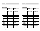
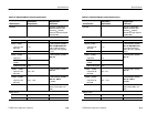
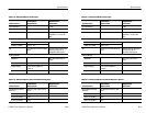
Table 5–1: Input/Output (Cont.)
Characteristics
Supplemental
Information
Performance
Requirements
Max volts from Loop-
Through common
terminal to chassis
2 V rms at mains frequency. Rejection ratio of common-
to-chassis in floating
ground mode, ≥34 dB at
mains frequency.
Max DC Output Voltage
Aux Video Out
±0.5 V into 75 W.
Pix Mon Out
±0.5 V into 75 W.
Line strobe; no input signal.
Remote Control
Interface Standard RS232 / RS422.
Control Enable Ground Closures and Pre-
sets.
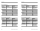
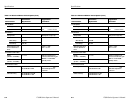
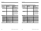
Table 5–2: Waveform Monitor Vertical System
Characteristics
Performance
Requirements
Supplemental
Information
Return Loss
CH A, B1, B2, or B3 >40 dB DC to 5 MHz.
(Terminated in 75 W.)
Aux Video In, Aux
Video Out, & Pix Mon
Out
>34 dB DC to 5 MHz. Instrument On only.
Ext. Sync Input >46 dB to 5 MHz.
Loop-Through Isolation >80 dB at F
SC,
between
channels and between
each channel and EXT
REF. Measured externally.
Specifications
5–2
1780R-Series Operator’s Manual
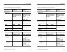
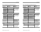
Table 5–1: Input/Output (Cont.)
Characteristics
Supplemental
Information
Performance
Requirements
Max volts from Loop-
Through common
terminal to chassis
2 V rms at mains frequency. Rejection ratio of common-
to-chassis in floating
ground mode, ≥34 dB at
mains frequency.
Max DC Output Voltage
Aux Video Out
±0.5 V into 75 W.
Pix Mon Out
±0.5 V into 75 W.
Line strobe; no input signal.
Remote Control
Interface Standard RS232 / RS422.
Control Enable Ground Closures and Pre-
sets.
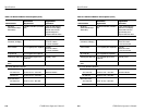
Table 5–2: Waveform Monitor Vertical System
Characteristics
Performance
Requirements
Supplemental
Information
Return Loss
CH A, B1, B2, or B3 >40 dB DC to 5 MHz.
(Terminated in 75 W.)
Aux Video In, Aux
Video Out, & Pix Mon
Out
>34 dB DC to 5 MHz. Instrument On only.
Ext. Sync Input >46 dB to 5 MHz.
Loop-Through Isolation >80 dB at F
SC,
between
channels and between
each channel and EXT
REF. Measured externally.