


Connectors, Controls, Indicators
2–6
1780R-Series Operator’s Manual
tion or variable sweep is selected, the cursor interval is magnified
correspondingly.
To change the large knob assignment from one cursor to another,
touch the quadrant labeled <CURSOR 1 / CURSOR 2>. The
current assignment is outlined by a box.
Timing cursors are not valid in Field mode.
For software versions 1.13 and up, installed in instruments SN
B020100 and up: Refer to (11) LINE SELECT for information on
Timing Cursors in Line Select mode.
NOTE. Detailed Timing and Voltage Cursor information is located in
Section 3.
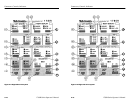
10. VOLTAGE CURSORS. This switch enables the voltage cursors.
The Voltage Cursor menu on the vectorscope CRT provides a
choice of cursors that track together or are positioned separately,
and a choice between absolute and relative readout. Cursor One
appears as a dashed horizontal line, and Cursor Two as a series of
two short dashes on the waveform monitor display. If vertical
gain is employed, the cursor interval is magnified accordingly.
To change the large knob assignment from one cursor to another,
touch the quadrant labeled <CURSOR 1 / CURSOR 2>. Current
assignment is outlined by a box.
11. LINE SELECT This switch enables the line select function,
which is available for both waveform and vectorscope. For
waveform display, the selected line is displayed first in a multiple
line display, and brightened in a field display. Alpha-numeric
readout indicates the selected line and field on both CRTs.
Additional line select information can be found in Section 3.
Full measurement functions are available in Line Select mode.
Large knob assignment is indicated by a circle, and is selected by
touching the line number area on the desired CRT screen.
Connectors, Controls, Indicators
2–6
1780R-Series Operator’s Manual
tion or variable sweep is selected, the cursor interval is magnified
correspondingly.
To change the large knob assignment from one cursor to another,
touch the quadrant labeled <CURSOR 1 / CURSOR 2>. The
current assignment is outlined by a box.
Timing cursors are not valid in Field mode.
For software versions 1.13 and up, installed in instruments SN
B020100 and up: Refer to (11) LINE SELECT for information on
Timing Cursors in Line Select mode.
NOTE. Detailed Timing and Voltage Cursor information is located in
Section 3.
10. VOLTAGE CURSORS. This switch enables the voltage cursors.
The Voltage Cursor menu on the vectorscope CRT provides a
choice of cursors that track together or are positioned separately,
and a choice between absolute and relative readout. Cursor One
appears as a dashed horizontal line, and Cursor Two as a series of
two short dashes on the waveform monitor display. If vertical
gain is employed, the cursor interval is magnified accordingly.
To change the large knob assignment from one cursor to another,
touch the quadrant labeled <CURSOR 1 / CURSOR 2>. Current
assignment is outlined by a box.
11. LINE SELECT This switch enables the line select function,
which is available for both waveform and vectorscope. For
waveform display, the selected line is displayed first in a multiple
line display, and brightened in a field display. Alpha-numeric
readout indicates the selected line and field on both CRTs.
Additional line select information can be found in Section 3.
Full measurement functions are available in Line Select mode.
Large knob assignment is indicated by a circle, and is selected by
touching the line number area on the desired CRT screen.