


Operating Instructions
3–54
1780R-Series Operator’s Manual
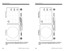
Left CRT display
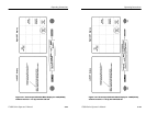
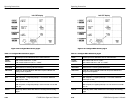
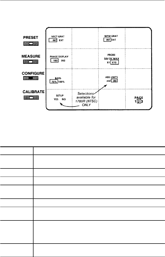
Figure 3–25: Configure Menu Screen, page 2
Table 3–7: Configure Menu Selections, page 2
BARS Vectorscope can be calibrated to 75% or 100% color bars.
PHASE
DISPLAY
360 = Phase reads from 0_ to 360_.
180 = Phase reads from +180_ to –179.95_.
VECT GRAT Select internal or external graticule illumination.
WFM GRAT Select internal or external graticule illumination.
ABS UNITS NTSC only. Choose millivolts or IRE units to express calibrator and
voltage cursor amplitudes.
PROBE Internal probe gain is X1 or X10.
X10 With 10X probe, 1 V signal at probe tip = 1 V on screen. Works like
probe input on 1480.
X1 With X1 probe, 1 V signal at probe tip = 1 V on screen.
With X10 probe, 5 V signal at probe tip = 0.5 V on screen. For use with
TTL, etc.
SETUP NTSC only. Select <YES> when there is 7.5% setup on the incoming
signal.
Operating Instructions
3–54
1780R-Series Operator’s Manual
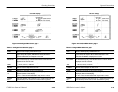
Left CRT display
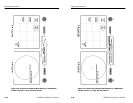
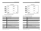
Figure 3–25: Configure Menu Screen, page 2
Table 3–7: Configure Menu Selections, page 2
BARS Vectorscope can be calibrated to 75% or 100% color bars.
PHASE
DISPLAY
360 = Phase reads from 0_ to 360_.
180 = Phase reads from +180_ to –179.95_.
VECT GRAT Select internal or external graticule illumination.
WFM GRAT Select internal or external graticule illumination.
ABS UNITS NTSC only. Choose millivolts or IRE units to express calibrator and
voltage cursor amplitudes.
PROBE Internal probe gain is X1 or X10.
X10 With 10X probe, 1 V signal at probe tip = 1 V on screen. Works like
probe input on 1480.
X1 With X1 probe, 1 V signal at probe tip = 1 V on screen.
With X10 probe, 5 V signal at probe tip = 0.5 V on screen. For use with
TTL, etc.
SETUP NTSC only. Select <YES> when there is 7.5% setup on the incoming
signal.