


Operating Instructions
1780R-Series Operator’s Manual
3–9
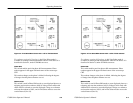
amplitude (3 dB), there are gaps in the horizontal and vertical axes.
This calibration aid makes it possible to check the –3 dB points of
the demodulator output amplifiers.
Differential Gain and Phase Measurements. The 1780R-Series provides
differential gain and phase measurements through the Measurement
menu, accessed by pushing the front-panel MEASURE button.
Instructions are given in Section 4.
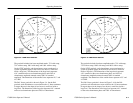
The 1780R-Series vector graticule is the same as the 1720-Series
vector graticule, and provides differential gain and phase markings,
so that approximate 1780R-Series measurements can also be made in
the same way as with the 1720. Differential gain (dG) and differen-
tial phase (dF) measurements can be made using the graticule
markings located at the outer edge of the B–Y axis (NTSC) or U axis
(PAL).
Differential gain appears as an elongation of the chrominance dot.
Measure the horizontal distance from end to end. Minor graticule
divisions represent 5% error, and major divisions represent 10%.
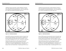
Differential Phase appears as a vectorial offset of the chrominance
dot. Measure angular difference, using the Differential Phase
graticule markings along the edge of the compass rose. Measuring
from the 0_ mark on the B–Y or U axis, each minor division
represents 2_ of error, the major divisions represent 10_, and the
dashed lines half-way in between represent 5_ of Differential Phase
error.
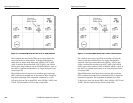
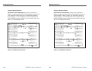
XY Measurements. The 1780R-Series vectorscope graticule contains
markings for measuring stereo audio phase and amplitude. The
dashed diagonal line is the measurement axis for errors less than
90_, and is terminated in amplitude targets that correspond to the
length of the X and Y axes. These target boxes, in the upper right
and lower left of the display, correspond to amplitude errors of 1/2
and 1 dB.
The upper half of the Y axis has markings in 10_ increments for
measuring the separation of the Lissajous. Both X and Y axes have
–3 dB markings, making it easy to check the bandpass of the
amplifiers. The 3 dB points are minor breaks in the line about 30%
of the distance from the graticule circle to the graticule center.
Operating Instructions
1780R-Series Operator’s Manual
3–9
amplitude (3 dB), there are gaps in the horizontal and vertical axes.
This calibration aid makes it possible to check the –3 dB points of
the demodulator output amplifiers.
Differential Gain and Phase Measurements. The 1780R-Series provides
differential gain and phase measurements through the Measurement
menu, accessed by pushing the front-panel MEASURE button.
Instructions are given in Section 4.
The 1780R-Series vector graticule is the same as the 1720-Series
vector graticule, and provides differential gain and phase markings,
so that approximate 1780R-Series measurements can also be made in
the same way as with the 1720. Differential gain (dG) and differen-
tial phase (dF) measurements can be made using the graticule
markings located at the outer edge of the B–Y axis (NTSC) or U axis
(PAL).
Differential gain appears as an elongation of the chrominance dot.
Measure the horizontal distance from end to end. Minor graticule
divisions represent 5% error, and major divisions represent 10%.
Differential Phase appears as a vectorial offset of the chrominance
dot. Measure angular difference, using the Differential Phase
graticule markings along the edge of the compass rose. Measuring
from the 0_ mark on the B–Y or U axis, each minor division
represents 2_ of error, the major divisions represent 10_, and the
dashed lines half-way in between represent 5_ of Differential Phase
error.
XY Measurements. The 1780R-Series vectorscope graticule contains
markings for measuring stereo audio phase and amplitude. The
dashed diagonal line is the measurement axis for errors less than
90_, and is terminated in amplitude targets that correspond to the
length of the X and Y axes. These target boxes, in the upper right
and lower left of the display, correspond to amplitude errors of 1/2
and 1 dB.
The upper half of the Y axis has markings in 10_ increments for
measuring the separation of the Lissajous. Both X and Y axes have
–3 dB markings, making it easy to check the bandpass of the
amplifiers. The 3 dB points are minor breaks in the line about 30%
of the distance from the graticule circle to the graticule center.