


Operating Instructions
1780R-Series Operator’s Manual
3–19
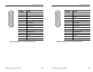
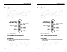
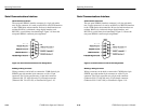
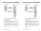
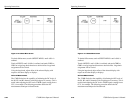
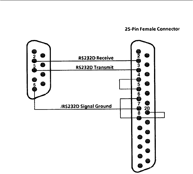
9-Pin Male Connector
Figure 3–10: Serial Interface Connector Wiring Converter
Serial Remote Information
1780R-Series instrument configurations can be stored at (and
retrieved from) a remote location. To accomplish this, the 1780R-Se-
ries is connected to a host computer through a serial port that
supports RS-232 or RS-422 standards.
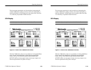
All front-panel controls operate in their usual manner during remote
operation, so remote selections may be changed with the front-panel
controls. Front-panel LED indicators light to show the current
selection.
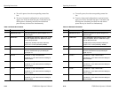
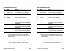
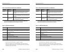
Commands to the 1780R-Series and its responses are listed in Tables
3–3 and 3–4.
Operating Instructions
1780R-Series Operator’s Manual
3–19
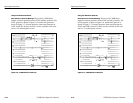
9-Pin Male Connector
Figure 3–10: Serial Interface Connector Wiring Converter
Serial Remote Information
1780R-Series instrument configurations can be stored at (and
retrieved from) a remote location. To accomplish this, the 1780R-Se-
ries is connected to a host computer through a serial port that
supports RS-232 or RS-422 standards.
All front-panel controls operate in their usual manner during remote
operation, so remote selections may be changed with the front-panel
controls. Front-panel LED indicators light to show the current
selection.
Commands to the 1780R-Series and its responses are listed in Tables
3–3 and 3–4.