


Connectors, Controls, Indicators
1780R-Series Operator’s Manual
2–7
Different lines can be displayed on the waveform and vector-
scope CRTs, when that function is selected via the Line Select
menu by touching <WFM = VECT> until <NO> is outlined.
For software versions 1.13 and up, installed in instruments SN
B020100 and up: For ease in viewing the Timing Cursors while
in Line Select mode, the Timing Cursor dots are positioned on
the Voltage Cursors. Upon entering Line Select mode with
Timing Cursors on, the Voltage Cursors are automatically
enabled.
For software versions 1.13 and up: A dual Line Select mode is
available for making ICPM measurements when in Line Select. It
is described in Section 4, under ICPM Measurement.
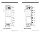
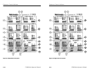
12. PHASE SHIFT. This switch enables the precision phase shift
measurements. Phase readout appears in the upper left corner of
the vectorscope CRT. This readout changes as the phase is
shifted. For SCH operation, the phase ranges from 180_ to 180_.
For Vector, the configure menu offers a choice of two phase
displays: 180_ to 180_ or 0_ to 360_.
13. REFERENCE SET. This switch is used in Phase Shift, Voltage
Cursor, and Line Select modes. In Phase Shift, it stores the
currently displayed phase as a reference and resets the readout to
0.00. In Voltage Cursor mode with <RELATIVE> selected, it
stores the currently displayed voltage as a reference and resets
the readout to 100% (0 dB). In Line Select mode, it is used to
access the vertical interval (line 19).
14. KNOB. The Precision Measurement control (large knob) operates
with selected functions to provide continuous adjustment.
15. < > These switches operate with selected functions to provide
single-step adjustment. The readout increments are the same as
those for the Precision Measurement Control.
Connectors, Controls, Indicators
1780R-Series Operator’s Manual
2–7
Different lines can be displayed on the waveform and vector-
scope CRTs, when that function is selected via the Line Select
menu by touching <WFM = VECT> until <NO> is outlined.
For software versions 1.13 and up, installed in instruments SN
B020100 and up: For ease in viewing the Timing Cursors while
in Line Select mode, the Timing Cursor dots are positioned on
the Voltage Cursors. Upon entering Line Select mode with
Timing Cursors on, the Voltage Cursors are automatically
enabled.
For software versions 1.13 and up: A dual Line Select mode is
available for making ICPM measurements when in Line Select. It
is described in Section 4, under ICPM Measurement.
12. PHASE SHIFT. This switch enables the precision phase shift
measurements. Phase readout appears in the upper left corner of
the vectorscope CRT. This readout changes as the phase is
shifted. For SCH operation, the phase ranges from 180_ to 180_.
For Vector, the configure menu offers a choice of two phase
displays: 180_ to 180_ or 0_ to 360_.
13. REFERENCE SET. This switch is used in Phase Shift, Voltage
Cursor, and Line Select modes. In Phase Shift, it stores the
currently displayed phase as a reference and resets the readout to
0.00. In Voltage Cursor mode with <RELATIVE> selected, it
stores the currently displayed voltage as a reference and resets
the readout to 100% (0 dB). In Line Select mode, it is used to
access the vertical interval (line 19).
14. KNOB. The Precision Measurement control (large knob) operates
with selected functions to provide continuous adjustment.
15. < > These switches operate with selected functions to provide
single-step adjustment. The readout increments are the same as
those for the Precision Measurement Control.