


Operating Instructions
1780R-Series Operator’s Manual
3–43
Waveform Calibration Procedure
1. Apply a video signal to a 1780R-Series input channel and select
that channel for display.
2. Push the front-panel CONFIGURE button and touch <FIXED
CAL AMPL> until 1000 (1.0 volt) is outlined.
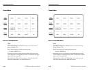
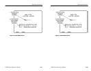
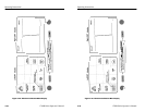
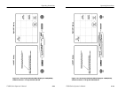
3. Push the front-panel CALIBRATE button. If Password operation
is enabled, enter the password now. The Waveform Calibration
menu will be displayed, as shown in Figure 3–20.
4. <READOUT INTENSITY> will be circled, and a test readout
will be displayed. Use the large knob to adjust the readout to the
desired intensity. (It is necessary to adjust readout intensity in this
manner; the front-panel INTENSITY control is used to adjust
signal intensity only.)
Perform Step 5 for SN below B020245 only:
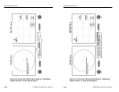
5. Touch <HORIZ POS KNOB CAL> to calibrate the Horizontal
Position knob. A menu will be displayed on the waveform CRT.
Center the Horizontal Position control by turning the knob and
releasing, allowing the spring (not necessarily the signal display)
to return to midpoint of its range. Then touch the area labeled
<CENTER HORIZONTAL POSITION KNOB, THEN PRESS
HERE>. This tells the microprocessor that the knob is now at the
midpoint, or zero point, of its range. This zero point is referred to
as the Dead Zone, and its tolerance can be varied by touching
<INCREASE> or <DECREASE>. The value changes in single
step increments from the smallest possible setting of 1 unit up to
16 units, and current value is shown on the readout. A beep
sounds when the Dead Zone has been increased or decreased as
much as possible. As the Dead Zone is increased, the control
must be turned more before it will respond, but will also return to
center more readily after it is turned.
6. Touch <TRACE ROTATION> to obtain a test axis, then use the
large knob to align the display to the graticule.
Operating Instructions
1780R-Series Operator’s Manual
3–43
Waveform Calibration Procedure
1. Apply a video signal to a 1780R-Series input channel and select
that channel for display.
2. Push the front-panel CONFIGURE button and touch <FIXED
CAL AMPL> until 1000 (1.0 volt) is outlined.
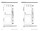
3. Push the front-panel CALIBRATE button. If Password operation
is enabled, enter the password now. The Waveform Calibration
menu will be displayed, as shown in Figure 3–20.
4. <READOUT INTENSITY> will be circled, and a test readout
will be displayed. Use the large knob to adjust the readout to the
desired intensity. (It is necessary to adjust readout intensity in this
manner; the front-panel INTENSITY control is used to adjust
signal intensity only.)
Perform Step 5 for SN below B020245 only:
5. Touch <HORIZ POS KNOB CAL> to calibrate the Horizontal
Position knob. A menu will be displayed on the waveform CRT.
Center the Horizontal Position control by turning the knob and
releasing, allowing the spring (not necessarily the signal display)
to return to midpoint of its range. Then touch the area labeled
<CENTER HORIZONTAL POSITION KNOB, THEN PRESS
HERE>. This tells the microprocessor that the knob is now at the
midpoint, or zero point, of its range. This zero point is referred to
as the Dead Zone, and its tolerance can be varied by touching
<INCREASE> or <DECREASE>. The value changes in single
step increments from the smallest possible setting of 1 unit up to
16 units, and current value is shown on the readout. A beep
sounds when the Dead Zone has been increased or decreased as
much as possible. As the Dead Zone is increased, the control
must be turned more before it will respond, but will also return to
center more readily after it is turned.
6. Touch <TRACE ROTATION> to obtain a test axis, then use the
large knob to align the display to the graticule.