


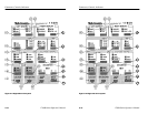

Connectors, Controls, Indicators
2–14
1780R-Series Operator’s Manual
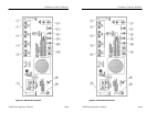
34. WAVEFORM (Control). Use this knob to control the amount of
variable gain when VAR is selected.
35. VECTOR (Control). Use this knob to control the amount of
variable gain when VAR is selected.
36. VAR / MAX (Switch). Push and release this switch to turn on the
vectorscope variable gain, which is controlled by the Vector
knob. Push and hold to disable the variable and set the vector-
scope gains to maximum.
Filter
NOTE. The following switch groups are companion switches: AUX /
DIFF / LPASS & FLAT / LUM / CHROM
Refer to the preceding instructions entitled Companion Switch
Example.
37. AUX / DIFF / LPASS. Push and release this switch to toggle
through the following selections: Aux Video In (signal is input
after the video filters), Differentiated step (linearity steps are
translated into spikes for amplitude comparisons), and Low-pass
filter (300 kHz bandwidth).
38. FLAT / LUM / CHROM. Push and release this switch to toggle
through the following selections: Flat (unfiltered video signal),
Luminance (chrominance filtered out), and Chrominance
(luminance filtered out). Push and hold to select a multiple filter
display, described in Table 2–3.
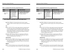
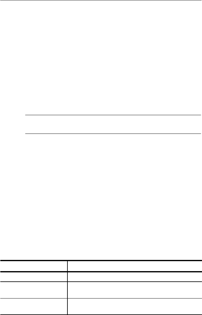
Table 2–3: Multiple Filter Displays
Display Possible Switch Settings
ONE LINE or FIELD Flat/Lum overlay.
TWO LINE or FIELD Flat filtered displayed first (left portion of screen), then
luminance filtered.
THREE LINE or FIELD Flat filtered displayed first, followed by luminance filtered
and chrominance filtered.
Connectors, Controls, Indicators
2–14
1780R-Series Operator’s Manual
34. WAVEFORM (Control). Use this knob to control the amount of
variable gain when VAR is selected.
35. VECTOR (Control). Use this knob to control the amount of
variable gain when VAR is selected.
36. VAR / MAX (Switch). Push and release this switch to turn on the
vectorscope variable gain, which is controlled by the Vector
knob. Push and hold to disable the variable and set the vector-
scope gains to maximum.
Filter
NOTE. The following switch groups are companion switches: AUX /
DIFF / LPASS & FLAT / LUM / CHROM
Refer to the preceding instructions entitled Companion Switch
Example.
37. AUX / DIFF / LPASS. Push and release this switch to toggle
through the following selections: Aux Video In (signal is input
after the video filters), Differentiated step (linearity steps are
translated into spikes for amplitude comparisons), and Low-pass
filter (300 kHz bandwidth).
38. FLAT / LUM / CHROM. Push and release this switch to toggle
through the following selections: Flat (unfiltered video signal),
Luminance (chrominance filtered out), and Chrominance
(luminance filtered out). Push and hold to select a multiple filter
display, described in Table 2–3.
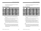
Table 2–3: Multiple Filter Displays
Display Possible Switch Settings
ONE LINE or FIELD Flat/Lum overlay.
TWO LINE or FIELD Flat filtered displayed first (left portion of screen), then
luminance filtered.
THREE LINE or FIELD Flat filtered displayed first, followed by luminance filtered
and chrominance filtered.