


Operating Instructions
3–10
1780R-Series Operator’s Manual
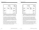
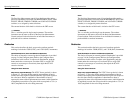
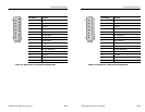
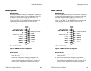
XY INPUT Connector. The rear-panel XY INPUT connector is a 15-pin,
sub-miniature, D-type connector that provides input to the
Horizontal and Vertical (X and Y) Amplifiers. They are balanced
(differential), DC-coupled, high impedance (>20 kW), un-terminated
inputs provided for audio applications. If AC coupling is desired,
external capacitors are required. These inputs are factory calibrated
for 0 dBm in 600 W but can be adjusted for any 600 W system
between 0 and 12 dBm. See Figure 3–5.
0 dBm is equal to 1 mW or 2.19 V peak-to-peak in 600 W. 12 dBm is
equal to 15.8 mW or 8.72 V peak-to-peak in 600 W.
To calibrate the 1780R-Series for a system other than 0 dBm,
perform step 38 of the Adjustment Procedure in the 1780R-Series
Service Manual, using a 1 kHz sine wave of the appropriate
amplitude.
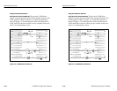
Inputs can be driven single-ended by driving either the + or – X and
Y inputs with the opposite polarity inputs grounded.
In addition, a single-ended, high-gain mode can be used for other,
primarily non-audio, applications. It can be accessed by installing
plug jumpers on J108 and J205 (on the Vectorscope board, see
Table 3–1) and inputting the signal on the +X and +Y inputs with the
–X and –Y inputs grounded.
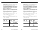
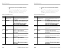
Table 3–1: Plug Jumpers for Vectorscope Board
Jumper
Number
Name Plug Position Purpose
J108 X Input Gain
Removed {
Installed
X gain is normal
X gain is in High Gain
position
J205 Y Input Gain
Removed {
Installed
Y gain is normal
Y gain is in High Gain
position
{
Factory installed position.
Operating Instructions
3–10
1780R-Series Operator’s Manual
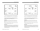
XY INPUT Connector. The rear-panel XY INPUT connector is a 15-pin,
sub-miniature, D-type connector that provides input to the
Horizontal and Vertical (X and Y) Amplifiers. They are balanced
(differential), DC-coupled, high impedance (>20 kW), un-terminated
inputs provided for audio applications. If AC coupling is desired,
external capacitors are required. These inputs are factory calibrated
for 0 dBm in 600 W but can be adjusted for any 600 W system
between 0 and 12 dBm. See Figure 3–5.
0 dBm is equal to 1 mW or 2.19 V peak-to-peak in 600 W. 12 dBm is
equal to 15.8 mW or 8.72 V peak-to-peak in 600 W.
To calibrate the 1780R-Series for a system other than 0 dBm,
perform step 38 of the Adjustment Procedure in the 1780R-Series
Service Manual, using a 1 kHz sine wave of the appropriate
amplitude.
Inputs can be driven single-ended by driving either the + or – X and
Y inputs with the opposite polarity inputs grounded.
In addition, a single-ended, high-gain mode can be used for other,
primarily non-audio, applications. It can be accessed by installing
plug jumpers on J108 and J205 (on the Vectorscope board, see
Table 3–1) and inputting the signal on the +X and +Y inputs with the
–X and –Y inputs grounded.
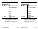
Table 3–1: Plug Jumpers for Vectorscope Board
Jumper
Number
Name Plug Position Purpose
J108 X Input Gain
Removed {
Installed
X gain is normal
X gain is in High Gain
position
J205 Y Input Gain
Removed {
Installed
Y gain is normal
Y gain is in High Gain
position
{
Factory installed position.