


Specifications
5–18
1780R-Series Operator’s Manual
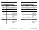
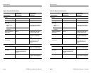
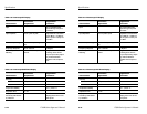
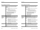
Table 5–8: Vectorscope XY Display
Characteristics
Performance
Requirements
Supplemental
Information
Input DC coupled differential
inputs through rear-panel
connector.
Input Amplitude 2 to 9 V peak-to-peak. Adjustable full scale deflec-
tion 0 dBm to +12 dBm for
600 W system. Factory set
to 0 dBm.
Maximum Input Voltage 15 V combined peak signal and
DC.
Frequency Response DC to >500 kHz. 3 dB point.
X and Y Input Phase
Matching
< a trace width of separation at
20 kHz.
Single-ended. Phase
matching above 20 kHz
may be improved by adjust-
ing Vertical Deflection
Amplifier VHF Compensa-
tion.
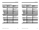
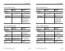
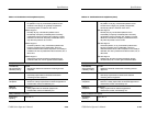
Table 5–9: Vectorscope SCH Phase Display
Characteristics
Performance
Requirements
Supplemental
Information
Accuracy
Absolute
±5_ phase at 25_ C.
Relative
±2_.
Temperature Stability
±0.1_ phase/_C.
Acquisition Time ≤1 sec.
Display Phase Error
Caused by CRT Geome-
try Variations
±1.25_ calibrated for zero
display phase error at zero
SCH phase.
Specifications
5–18
1780R-Series Operator’s Manual
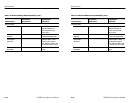
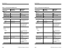
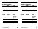
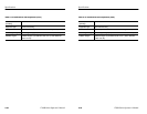
Table 5–8: Vectorscope XY Display
Characteristics
Performance
Requirements
Supplemental
Information
Input DC coupled differential
inputs through rear-panel
connector.
Input Amplitude 2 to 9 V peak-to-peak. Adjustable full scale deflec-
tion 0 dBm to +12 dBm for
600 W system. Factory set
to 0 dBm.
Maximum Input Voltage 15 V combined peak signal and
DC.
Frequency Response DC to >500 kHz. 3 dB point.
X and Y Input Phase
Matching
< a trace width of separation at
20 kHz.
Single-ended. Phase
matching above 20 kHz
may be improved by adjust-
ing Vertical Deflection
Amplifier VHF Compensa-
tion.
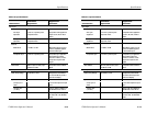
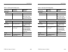
Table 5–9: Vectorscope SCH Phase Display
Characteristics
Performance
Requirements
Supplemental
Information
Accuracy
Absolute
±5_ phase at 25_ C.
Relative
±2_.
Temperature Stability
±0.1_ phase/_C.
Acquisition Time ≤1 sec.
Display Phase Error
Caused by CRT Geome-
try Variations
±1.25_ calibrated for zero
display phase error at zero
SCH phase.