Connectors, Controls, Indicators
2–16
1780R-Series Operator’s Manual
Rear Panel Connectors
Connectors CH A, CH B1, CH B2, CH B3, EXT REF, and CW are
high impedance bridging loop-through inputs. CH A, CH B1,
CH B2, and CH B3 have either a grounded or floating shield,
depending on the position of the grounding screw, which is located
between the BNC connectors.
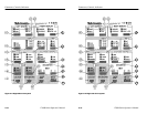
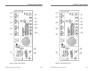
The following connector locations are shown in Figure 2–3.
1. CH A. CH A accepts composite or component video signals.
2. CH B1. CH B1 accepts composite or component video signals.
3. CH B2. CH B2 accepts composite or component video signals.
4. CH B3. CH B3 accepts composite or component video signals.
5. XY INPUT. XY is a 15-pin D-type connector used as a high
impedance input for the 600 W balanced audio. XY operation is
described in Section 3. The connector pinout is shown in Figure
3–5 on page 3–11.
6. EXT CW REF. CW connector accepts input for continuous
subcarrier signal. Provides an external phase reference signal.
7. LINE STRB OUT. LINE STRB OUT is a TTL output that
provides a negative-going pulse for the selected line(s) when
Line Select is used. When Line Select is off, the output level is
low.
8. AUX OUT. AUX OUT provides a 75 W video signal output
before filtering. AUX OUT can be used with the AUX IN to use
custom filters.
9. PIX MON OUT. PIX MON OUT connector provides a 75 W
output to drive a picture monitor. The signal is output before
filtering, and has a bright-up pulse added when Line Select is
used.
10. AUX IN. AUX IN provides a 75 W input for video signals to the
waveform monitor. Signal is inserted after the internal filters.
11. EXT REF. External Reference connector accepts either
composite sync or black burst.


