


Operating Instructions
3–14
1780R-Series Operator’s Manual
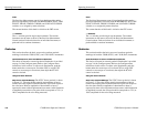
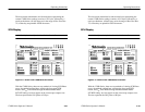
of the bar. Use the ±2% and ±5% graticule marks to quantify the
peak-to-peak deviation of the bar top (tilt or rounding) within the
structure. The vertical gain can be increased to measure small errors.
(When the X5 setting is selected, the graticule marks correspond to
±0.4% and ±1%.)
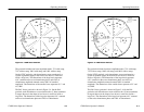
Line-time distortion measurements can also be made using the
voltage cursors in the RELATIVE mode. Define the amplitude
difference between blanking level and the bar center as 100%. Now
move both of the cursors to measure the peak-to-peak tilt. This
number is the line-time distortion. Remember to ignore the first and
last ms of the bar. The time cursors can be used to locate the
appropriate time interval in the center of the bar. Set the time
separation to 16 ms, and put the time cursors in the TRACK mode.
Move the two cursors together until they are centered on the bar.
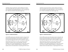
Line-time distortion-PAL. Line-time distortion in PAL systems is
measured with a signal that contains a 10 ms or 25 ms white bar. The
measurement methods given here quote the maximum departure of
the bar top from the level at the center of the line bar as the amount
of distortion, but they can be adapted for peak-to-peak measure-
ments. To make a measurement, measure the maximum deviation
from the center of the bar, and express that number as a percentage
of the level at bar center. The variable gain can be used to normalize
the center of the bar to 500 or 1000 mV. Deviations in the top of the
bar can then be read directly off the graticule in percent. Ignore the
first and last ms of the bar.
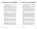
Line-time distortion measurements can also be made using the
voltage cursors in the RELATIVE mode. Define the amplitude
difference between blanking level and the bar center as 100%. Leave
one cursor at the bar center, and move the other cursor to measure
the peak positive and peak negative deviations in the top of the bar.
The largest of these numbers (ignore the sign) is the amount of
line-time distortion. The time cursors can be used to locate the
appropriate time interval in the center of the bar. Set the time
separation to the bar time (usually 10 ms or 25 ms) minus 2 ms. Put
the time cursors in the TRACK mode, and move the two cursors
together until they are centered on the bar.
Operating Instructions
3–14
1780R-Series Operator’s Manual
of the bar. Use the ±2% and ±5% graticule marks to quantify the
peak-to-peak deviation of the bar top (tilt or rounding) within the
structure. The vertical gain can be increased to measure small errors.
(When the X5 setting is selected, the graticule marks correspond to
±0.4% and ±1%.)
Line-time distortion measurements can also be made using the
voltage cursors in the RELATIVE mode. Define the amplitude
difference between blanking level and the bar center as 100%. Now
move both of the cursors to measure the peak-to-peak tilt. This
number is the line-time distortion. Remember to ignore the first and
last ms of the bar. The time cursors can be used to locate the
appropriate time interval in the center of the bar. Set the time
separation to 16 ms, and put the time cursors in the TRACK mode.
Move the two cursors together until they are centered on the bar.
Line-time distortion-PAL. Line-time distortion in PAL systems is
measured with a signal that contains a 10 ms or 25 ms white bar. The
measurement methods given here quote the maximum departure of
the bar top from the level at the center of the line bar as the amount
of distortion, but they can be adapted for peak-to-peak measure-
ments. To make a measurement, measure the maximum deviation
from the center of the bar, and express that number as a percentage
of the level at bar center. The variable gain can be used to normalize
the center of the bar to 500 or 1000 mV. Deviations in the top of the
bar can then be read directly off the graticule in percent. Ignore the
first and last ms of the bar.
Line-time distortion measurements can also be made using the
voltage cursors in the RELATIVE mode. Define the amplitude
difference between blanking level and the bar center as 100%. Leave
one cursor at the bar center, and move the other cursor to measure
the peak positive and peak negative deviations in the top of the bar.
The largest of these numbers (ignore the sign) is the amount of
line-time distortion. The time cursors can be used to locate the
appropriate time interval in the center of the bar. Set the time
separation to the bar time (usually 10 ms or 25 ms) minus 2 ms. Put
the time cursors in the TRACK mode, and move the two cursors
together until they are centered on the bar.