


28
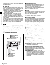
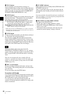
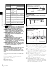
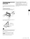
Rear Panel
Chapter 2 Names and Functions of Parts
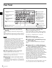
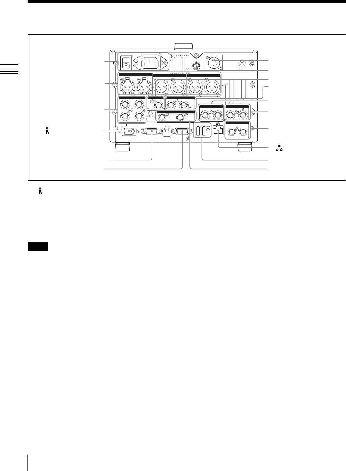
Rear Panel
a (i.LINK) S400 connector (6-pin, IEEE1394
compliant)
Connect a computer or other device, using an i.LINK
cable.
When the PDBK-201 option board is installed, i.LINK TS
(HDV) signals can be input and output via this connector.
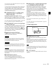
• When this unit is connected to a device with a 6-pin
i.LINK connector by an i.LINK cable, before
unplugging the i.LINK cable, first power off the device
and disconnect the power plug from the outlet. If the
i.LINK cable is unplugged with the device power plug
still connected, a current from an excessive voltage (8 to
40 V) output from the i.LINK connector of the device
flows into this unit. This may cause a failure of the unit.
• When connecting this unit to a device with a 6-pin
i.LINK connector, connect to the 6-pin i.LINK
connector of the other device first.
b VIDEO CONTROL connector (D-sub-9-pin)
Connect an HKDV-900 video control unit.
See page 174 for correspondence between setting items of
HKDV-900 and setup menu of this unit.
c REMOTE(9P) (remote control 9-pin) connector
(D-sub 9-pin)
To control this unit from a controller or VTR supporting
the RS-422A Sony 9-pin VTR protocol, connect the device
to this connector.
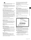
d DC IN 12V connector (XLR 4-pin, male)
Connect to a DC power source of 12 V.
When using the BKP-L551 Battery Adaptor to mount a
battery pack, connect the power cable of the BKP-L551.
For details, see “Supplying power” on page 32.
e REMOTE connector (4-pin)
Supplies power to the RM-280 Editing Controller.
f SD/HDSDI INPUT (SDSDI/HDSDI signal input)
connector (BNC type)
This inputs an SDSDI or HDSDI format video/audio
signal.
g HDSDI OUTPUT 1, 2 (SUPER) (HDSDI signal
output 1, 2 (superimpose)) connectors (BNC type)
These output HDSDI format video/audio signals.
When editing with two PDW-HD1500 units, connect a
cable between these connectors on the player unit and the
SD/HDSDI INPUT connector on the recorder unit.
You can superimpose timecodes, menu settings, error
messages, or other information on the output of the HDSDI
OUTPUT 2 (SUPER) connector with the setting for
CHAR SEL on the HOME page of the function menu or
with the setting for setup menu item 028 HD
CHARACTER. You can always disable to superimpose
the data independent of the setting for CHAR SEL with the
setting for setup menu item 028.
See “Basic Operations of the Function Menu” (page 48)
for more information about the CHAR SEL settings.
POWER
REMOTE(9P)
MAINTENANCE
VIDEO CONTROL
DC IN 12V
=
AC IN
REMOTE
ANALOG AUDIO INPUT
SDSDI OUTPUT
ANALOG AUDIO OUTPUT
12
12
(SUPER)
12
(SUPER)
12
AUDIO MONITOR
RL
1/2 3/4IN
1/2 3/4
OUT
DIGITAL AUDIO (AES/EBU) SD/HDSDI INPUT HDSDI OUTPUT
12
(SUPER)
COMPOSITE OUTPUT
IN
REF.VIDEO INPUT
IN OUT
TIME CODE
S400
1 Power supply section (see
page 29)
2 Analog audio signal input/
output section (see
page 30)
3 Digital audio signal input/
output section (see
page 30)
1 (i.LINK) S400 connector
2 VIDEO CONTROL connector
3 REMOTE(9P) connector
4 DC IN 12V connector
5 REMOTE connector
7 HDSDI OUTPUT 1, 2
(SUPER) connectors
8 COMPOSITE OUTPUT1, 2
(SUPER) connectors
9 REF.VIDEO INPUT
connectors
4 Timecode input/output
section (see page 30)
qa MAINTENANCE connectors
qs SDSDI OUTPUT1, 2
(SUPER) connectors
0 (network) connector
6 SD/HDSDI INPUT connector
Notes