


30
Rear Panel
Chapter 2 Names and Functions of Parts
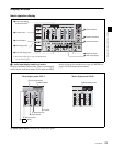
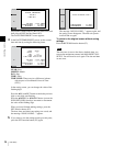
2 Analog audio signal input/output section
a ANALOG AUDIO INPUT 1, 2 connectors (XLR 3-
pin, female)
These input analog audio signals.
With A1 INPUT or A2 INPUT on page P2 AUDIO, and
A3 INPUT or A4 INPUT on page P3 AUDIO of the
function menu (see page 50), you can select whether the
signal input to connector 1 is assigned to audio channel 1or
3, and whether the signal input to connector 2 is assigned
to audio channel 2 or 4.
You can set the reference input level with the maintenance
menu item M37: AUDIO CONFIG (see page 144).
(Factory default setting: +4 dB)
Microphone settings
If you have connected a microphone to this unit, you can
set input level, AGC, and limiter values for the
microphone with setup menu items 834, 839, 840, and 841
(see page 140).
An unpleasant sound may be output if you have connected
a microphone to the ANALOG AUDIO INPUT 1 or 2
connector and power the microphone on with the input
level too high. Check the input level setting before
connecting a microphone.
b ANALOG AUDIO OUTPUT 1, 2 connectors (XLR
3-pin, male)
These output analog audio signals.
When the unit is shipped from the factory, the 1 connector
is set to audio channel 1, and the 2 connector is set to audio
channel 2. You can change these settings with setup menu
item 824 ANALOG LINE OUTPUT SELECT (see
page 139).
You can set the output level with the maintenance menu
item M37: AUDIO CONFIG (see page 144). (Factory
default setting: +4 dB)
Non-audio signals are muted.
c AUDIO MONITOR R, L connectors (XLR 3-pin,
male)
This outputs an audio signal for monitoring.
The monitored channel is selected with MONITR L and
MONITR R on page P2 AUDIO of the function menu.
See “Basic Operations of the Function Menu” (page 48)
for more information.
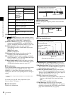
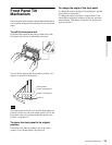
3 Digital audio signal input/output section
a DIGITAL AUDIO (AES/EBU) IN (digital audio
input) 1/2, 3/4 connectors (BNC type)
These input AES/EBU format digital audio signals. The
left connector (1/2) corresponds to audio channels 1 and 2,
and the right connector (3/4) corresponds to audio
channels 3 and 4.
b DIGITAL AUDIO (AES/EBU) OUT (digital audio
output) 1/2, 3/4 connectors (BNC type)
These output AES/EBU format digital audio signals.
When the unit is shipped from the factory, the 1/2
connector is set to audio channel 1/2, and the 3/4 connector
is set to audio channel 3/4. You can change these settings
with setup menu item 827 AES/EBU AUDIO OUTPUT
SELECT (see page 139).
To treat the input and output signals of these connectors as
non-audio signals, set the maintenance menu item M37:
AUDIO CONFIG >M372: NON-AUDIO INPUT
(recording) (see page 144) and setup menu item 823 NON-
AUDIO FLAG PB (playback).
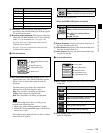
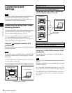
4 Timecode input/output section
a TIME CODE IN connector (BNC type)
This inputs an SMPTE timecode generated by an external
device.
b TIME CODE OUT connector (BNC type)
This outputs the following timecode, depending on the
operating state of this unit.
During playback: Playback timecode
Note
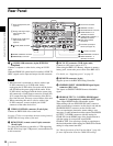
ANALOG AUDIO INPUT
ANALOG AUDIO OUTPUT
1212
AUDIO MONITOR
RL
1 ANALOG AUDIO INPUT 1, 2 connectors
2 ANALOG AUDIO OUTPUT 1, 2
connectors
3 AUDIO MONITOR R, L connectors
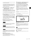
1/2 3/4IN
1/2 3/4
OUT
DIGITAL AUDIO (AES/EBU)
1 DIGITAL AUDIO (AES/EBU) IN 1/2, 3/4
connectors
2 DIGITAL AUDIO (AES/EBU) OUT 1/2, 3/4
connectors
IN OUT
TIME CODE
1 TIME CODE IN connector
2 TIME CODE OUT
connector