


50
Basic Operations of the Function Menu
Chapter 3 Preparations
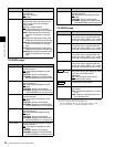
P3 AUDIO page
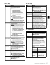
P4 AUDIO page
a) To enable this setting, the following settings are also required, in the same
way as for volume operations for channels 1 to 4.
- Set the VARIABLE switch of the front panel to “REC” or “PB”.
- Set setup menu item 131 AUDIO VOLUME to “EACH”.
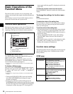
F5: SPEAKER Enables or disables output from this
unit’s speaker.
OFF
: Do not output
ON: Output
F6: LEVEL MT Specifies the position at which to
superimpose audio level meters in the
video monitor screen (in full-screen
display mode).
OFF
: Do not superimpose.
LEFT: Superimpose the audio level
meters of 2 channels on the left side.
RIGHT: Superimpose the audio level
meters of 2 channels on the right
side.
LEFT(4): Superimpose the audio level
meters of 4 channels on the left side.
RIGHT(4): Superimpose the audio level
meters of 4 channels on the right
side.
LEFT(8): Superimpose the audio level
meters of 8 channels on the left side.
RIGHT(8): Superimpose the audio level
meters of 8 channels on the right
side.
Item Setting
F1: A3 INPUT Selects the audio input signal to assign
to audio channel 3.
SDI
: Audio signal embedded into SDI
signal
ANALOG1: Analog 1 audio signal
AES/EBU3: Signal input to the DIGITAL
AUDIO(AES/EBU) IN 3/4 connectors
F2: A4 INPUT Selects the audio input signal to assign
to audio channel 4.
SDI
: Audio signal embedded into SDI
signal
ANALOG2: Analog 2 audio signal
AES/EBU4: Signal input to the DIGITAL
AUDIO(AES/EBU) IN 3/4 connectors
F3: A5 INPUT Selects the audio input signal to assign
to audio channel 5.
SDI
: Audio signal embedded into SDI
signal
ANALOG1: Analog 1 audio signal
AES/EBU1: Signal input to the DIGITAL
AUDIO(AES/EBU) IN 1/2 connectors
F4: A6 INPUT Selects the audio input signal to assign
to audio channel 6.
SDI
: Audio signal embedded into SDI
signal
ANALOG2: Analog 2 audio signal
AES/EBU2: Signal input to the DIGITAL
AUDIO(AES/EBU) IN 1/2 connectors
F5: A7 INPUT Selects the audio input signal to assign
to audio channel 7.
SDI
: Audio signal embedded into SDI
signal
ANALOG1: Analog 1 audio signal
AES/EBU3: Signal input to the DIGITAL
AUDIO(AES/EBU) IN 3/4 connectors
Item Setting
F6: A8 INPUT Selects the audio input signal to assign
to audio channel 8.
SDI
: Audio signal embedded into SDI
signal
ANALOG2: Analog 2 audio signal
AES/EBU4: Signal input to the DIGITAL
AUDIO(AES/EBU) IN 3/4 connectors
Item Setting
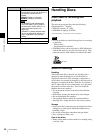
F1: A5 VOL
Sets the volume of audio channel 5.
a)
The volume can be adjusted within the
range from –200 to +200 (–∞ to +12 dB)
by turning the PUSH SET(S.SEL) knob.
F2: A6 VOL
Sets the volume of audio channel 6.
a)
The volume can be adjusted within the
range from –200 to +200 (–∞ to +12 dB)
by turning the PUSH SET(S.SEL) knob.
F3: A7 VOL
Sets the volume of audio channel 7.
a)
The volume can be adjusted within the
range from –200 to +200 (–∞ to +12 dB)
by turning the PUSH SET(S.SEL) knob.
F4: A8 VOL
Sets the volume of audio channel 8.
a)
The volume can be adjusted within the
range from –200 to +200 (–∞ to +12 dB)
by turning the PUSH SET(S.SEL) knob.
F5: MIX/SWAP
Specifies whether to perform audio
mixing according to the settings of setup
menu item 819 AUDIO INPUT
ARRANGE.
OFF
: Do not perform audio mixing.
ON: Perform audio mixing.
F5:
(Unassigned function button)
F6: AU METER Selects the display mode of the audio
level meters.
FULL: Display the range from –60 dB to
0 dB.
FINE: Display a magnified section with
0.25 dB step marks.
Item Setting
F1600
HD1500