


41
Connections and Settings
Chapter 3 Preparations
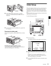
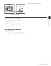
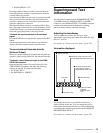
Using the editing functions of the
recorder (controlling through
REMOTE(9P) connector)
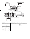
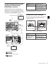
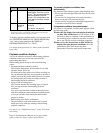
The following figure shows a cut editing system
comprising this unit as a player, and an HDW-M2000/
M2000P unit as a recorder. In this example, video and
audio signals are connected by HDSDI, and control signals
are transferred via the REMOTE(9P) connector.
For details of HDW-M2000/M2000P settings, refer to the
HDW-M2000/M2000P Operation Manual.
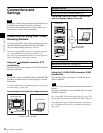
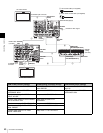
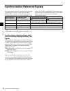
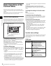
Connections for pool coverage
The following figure shows an example of connections for
pool coverage, with the PDW-700 Professional Disc
Camcorder connected.
75Ω
POWER
REMOTE(9P)VIDEO CONTROL
DC IN 12V
=
AC IN
REMOTE
ANALOG AUDIO INPUT
SDSDI OUTPUT
ANALOG AUDIO OUTPUT
12
12
(SUPER)
12
(SUPER)
12
AUDIO MONITOR
RL
1/2 3/4IN
1/2 3/4
OUT
DIGITAL AUDIO (AES/EBU) HDSDI OUTPUT
12
(SUPER)
COMPOSITE OUTPUT
IN
REF.VIDEO INPUT
IN OUT
TIME CODE
S400
MAINTENANCE
SD/HDSDI INPUT
REF.VIDEO
INPUT
REMOTE 1-OUT(9P)
HDSDI
OUTPUT 3
(SUPER)
REMOTE(9P)
REF.VIDEO
INPUT
REF VIDEO
INPUT
HDSDI
INPUT
HDSDI
OUTPUT2
(SUPER)
HDSDI
OUTPUT1
1
1
1
1
1
2
HD video monitor
To HDSDI input connector
PDW-F1600 or PDW-HD1500
(this unit, player)
Reference
video signal
HDW-M2000
(recorder)
To HDSDI
input
connector
1: 75Ω coaxial cable (not supplied)
2: 9-pin remote control cable (not supplied)
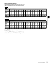
HD video monitor
HDW-M2000 (recorder)
setting
Settings on this unit
REMOTE 1 (9P) button:
Unlit
Remote control switch:
REMOTE (see page 18)
Setup menu item 214
REMOTE INTERFACE: 9PIN
PDW-700 (camcorder)
setting
Settings on this unit
HDSDI REMOTE I/F on
page CAM CONFIG 1 of
the MAINTENANCE menu:
other than OFF
Remote control switch:
REMOTE (see page 18)
Setup menu item 214
REMOTE INTERFACE: SDI
75Ω coaxial cable (not supplied)
To SDI OUT 1 connector
PDW-700
PDW-F1600 or PDW-
HD1500 (this unit)
To SD/HDSDI INPUT
connector