


49
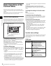
Basic Operations of the Function Menu
Chapter 3 Preparations
a) This is displayed only when TCG on page P5 TC of the function menu is
set to “INT”, and PRST/RGN is set to “PRESET”.
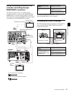
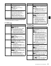
P1 VIDEO page
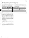
P2 AUDIO page
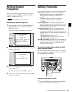
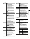
F4: CNTR SEL Selects the type of time data to display in
the time data display area.
TC
: Timecode
COUNTER: Elapsed recording or
playback time
UB: User bits
F5: TCG SET • When CNTR SEL is set to “TC” ,
displays a screen where you can set
the initial value of the timecode
generated by the internal timecode
generator
a)
(see page 43).
• When CNTR SEL is set to “UB” ,
displays a screen where you can set
timecode user bits
a)
(see page 44).
F6: (Unassigned function button)
Item Setting
F1: V INPUT Selects the video input signal.
HDSDI
: HDSDI signal
SDSDI: SDSDI signal
i.LINK: i.LINK signal (when the PDBK-
201 option board is installed)
SG: Test signal from internal signal
generator (Normally this item is not
displayed. It appears when you hold
the button down for 3 seconds.)
F2: VID. PROC Selects the method used to control the
internal video signal processor and make
related settings.
LOCAL
: Use the function menu to
change settings.
MENU: Use the setup menu to change
settings.
F3: VIDEO Sets the output level for HD/SD video
signals (range –∞ to +3 dB).
PRESET
: Set the video signal output
level to a preset value, regardless of
manual setting.
Manual setting: While the setting value
is flashing, turn the PUSH
SET(S.SEL) knob to adjust the video
signal output level.
F4: CHROMA Sets the output level for HD/SD chroma
signals (range –∞ to +3 dB).
PRESET
: Set the chroma signal output
level to a preset value, regardless of
manual setting.
Manual setting: While the setting value
is flashing, turn the PUSH
SET(S.SEL) knob to adjust the
chroma SETUP signal output level.
Item Setting
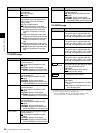
F5: HUE/CHRM
PHS
Sets the hue (chroma phase).
PRESET: Set the hue (chroma phase) to
a preset value, regardless of manual
setting.
Manual setting: While the setting value
is flashing, turn the PUSH
SET(S.SEL) knob to adjust the hue
(chroma phase) over the range
±30°.
F6: SETUP/
BLACK
Sets the HD/SD output black setup level
or black level.
PRESET
: Set the level to the preset
value, regardless of the manual
setting.
Manual setting: While the setting value
is flashing, turn the PUSH
SET(S.SEL) knob to set the black
setup level (in 59.94i/59.94P/
29.97P/23.98P mode) over the
range ±30 IRE or the black level (in
50i/50P/25P mode) over the range
±210 mV.
Item Setting
F1: A1 INPUT Selects the audio input signal to assign
to audio channel 1.
SDI
: Audio signal embedded into SDI
signal
ANALOG1: Analog 1 audio signal
AES/EBU1: Signal input to the DIGITAL
AUDIO(AES/EBU) IN 1/2 connectors
SG: Test signal from internal signal
generator (Normally this item is not
displayed. It appears when you hold
the button down for 3 seconds. The
test signal is assigned to audio
channels 1 to 8 simultaneously.)
Press one of the function buttons
corresponding to A1 INPUT to A8
INPUT again to stop output of the
test signal.
i.LINK: i.LINK signal (when the PDBK-
201 option board is installed)
F2: A2 INPUT Selects the audio input signal to assign
to audio channel 2.
SDI
: Audio signal embedded into SDI
signal
ANALOG2: Analog 2 audio signal
AES/EBU2: Signal input to the DIGITAL
AUDIO(AES/EBU) IN 1/2 connectors
F3: MONITR L Selects the channel to monitor as the left
monitor channel.
CH1
, CH2, CH3, CH4, CH5, CH6, CH7,
CH8
CH1/2, CH3/4, CH5/6, CH7/8 (MIX)
F4: MONITR R Selects the channel to monitor as the
right monitor channel.
CH1, CH2
, CH3, CH4, CH5, CH6, CH7,
CH8
CH1/2, CH3/4, CH5/6, CH7/8 (MIX)
Item Setting