


29
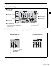
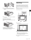
Rear Panel
Chapter 2 Names and Functions of Parts
See page 124 for more information about the setup menu
item 028 HD CHARACTER.
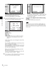
To treat the input and output signals of these connectors as
non-audio signals, set the maintenance menu item M37:
AUDIO CONFIG >M372: NON-AUDIO INPUT
(recording) (see page 144) and setup menu item 823 NON-
AUDIO FLAG PB (playback).
h COMPOSITE OUTPUT 1, 2 (SUPER) (analog
composite video output 1, 2 (superimpose))
connectors (BNC type)
Output analog composite video signals. You can
superimpose timecodes, menu settings, or error messages
on the output of the 2 (SUPER) connector when CHAR
SEL on the HOME page of the function menu is set to ON.
See “Basic Operations of the Function Menu” on page 48
for more information about the CHAR SEL setting.
i REF.VIDEO INPUT (reference video signal input)
connectors (BNC type)
The two connectors form a loop-through connection; when
a reference video signal is input to the left connector, the
same signal is input from the right connector ( ) to a
connected device. When no connection is made to the right
connector, the left connector is automatically terminated
with an impedance of 75 ohms.
j (network) connector (RJ-45 type)
This is a 10BASE-T/100BASE-TX/1000BASE-T
connector for network connection.
For safety, do not connect the connector for peripheral
device wiring that might have excessive voltage to this
port. Follow the instructions for this port.
Par mesure de sécurité, ne raccordez pas le connecteur
pour le câblage de périphériques pouvant avoir une tension
excessive à ce port. Suivez les instructions pour ce port.
Aus Sicherheitsgründen nicht mit einem Peripheriegerät-
Anschluss verbinden, der zu starke Spannung für diese
Buchse haben könnte. Folgen Sie den Anweisungen für
diese Buchse.
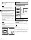
k MAINTENANCE connectors
These are the USB connectors for maintenance.
Connect a Windows USB keyboard or mouse (see
page 81), or a USB flash drive to access planning metadata
stored on the drive (see page 92).
l SDSDI OUTPUT 1, 2 (SUPER) (SDI signal outputs
1, 2 (superimpose)) connectors (BNC type)
These output SDSDI format video/audio signals.
When the unit is shipped from the factory, audio signal
output is eight channels with no switching, and RP188
timecode output is set to on. You can change these settings
with setup menu item 828 SDI AUDIO OUTPUT
SELECT and setup menu item 920 SD-SDI H-ANC
CONTROL.
The output from the 2 (SUPER) connector can have
timecode, menu settings, alarm messages, and other text
information superimposed. To turn superimposition off,
set CHAR SEL on the HOME page of the function menu
to “OFF”.
See “Items in the extended menu” (page 129) for more
information.
See “Basic Operations of the Function Menu” (page 48)
for more information.
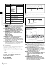
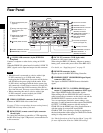
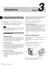
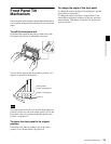
1 Power supply section
a POWER (main power) switch
Press the : side to power on the unit. Press the a side to
power off.
When using the unit, normally leave the POWER switch in
the : (on) position, and use the on/standby button on the
front panel to switch the unit between the operating state
and standby state.
Before turning the main power off, always check to be sure
that the unit is in the standby state, and then press the main
power switch to the a side.
b -AC IN connector
Connect to an AC power supply with the power cord (not
supplied).
CAUTION
ATTENTION
ACHTUNG
Note
POWER
AC IN
1 POWER switch
2 - AC IN connector