


VIS-CAM System
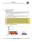
4 Preparing for Installation
1.3.3 Illumination
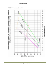
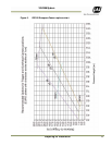
1.3.3 (a) TNF-31 Flash
The TNF-31 Flash generates light in wavelengths that are invisible to the human eye, but visible to
the camera. This makes the flash suitable for illuminating both oncoming and receding views of
traffic. Unlike near-infrared illuminators, the TNF-31 yields high contrast images of license plates
even if they have red characters on white or yellow backgrounds.
The TNF-31 Flash is automatically enabled whenever the TLS-300 Light Sensor determines that
ambient light is insufficient to produce a picture of usable quality. When the TNF-31 is enabled, it
fires every time the vehicle detector triggers the camera.
1.3.3 (b) White light LED.
JAI offers White LEDs mounted inside the camera enclosure. This option is usually employed when
certain rare color combinations on license plates do not yield sufficient contrast with the TNF-31
Flash option alone.
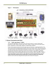
1.3.4 VJP-300 Junction Panel.
The VIS J-Panel is the central connection point for the VIS components. The J-Panel is a DIN-Rail
mounted PCB equipped with various interface terminals for interconnection of the VIS components;
this can be Ethernet connection, serial connection, TTL trigger feed and power supply. It offers the
possibility of manually selecting trigger polarity to the camera. Furthermore the J-Panel is equipped
with status LED’s and trigger switches for diagnostics and troubleshooting purposes.
1.3.5 RS485 Device Server.
The MOXA RS485 Device Server enables connection of RS485 serial devices to the Ethernet. The
purpose for the MOXA RS485 Device Server in the VIS system is to convert Ethernet to RS485
communication for the TLS-300 Light Sensor.
1.3.6 ENSetup Program.
The ENSetup Program is an Ethernet based software tool specifically designed to assist the installer
with VIS installation, and EN-Camera configuration and diagnostics. The program runs on a standard
PC / Laptop with Windows XP installed. Refer to Section 4 on page 31 of this manual and the VISCAM
300/400 EN Setup Manual for details.
1.4 Operational Overview.
During installation, the VISCAM and the optional light source are aimed at the area of the road
where vehicles and their license plates are most likely to pass through. The Traffic Light Sensor
continually registers the ambient light. The camera uses this information to set up exposure
variables to ensure an optimal image of the vehicle and license plate. During transition from day to
night the camera enables the optional TNF-31 Flash and/or white light LED’s to secure adequate
image quality during low ambient light conditions.
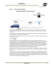
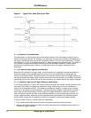
1.4.1 Trigger Mode
• A vehicle passes by a vehicle detector, sending a trigger to the VIS.
• The VIS employs a trigger to snap a video image of the vehicle and license plate when they are
optimally positioned in the camera field of view.
• The optional flash, if used, fires simultaneously with the camera to ensure correct exposure for
the image if the ambient lightning is too low.