


VIS-CAM System
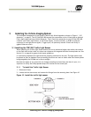
24 Installing the Vehicle Imaging Subsystem
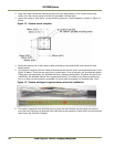
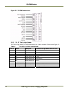
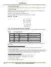
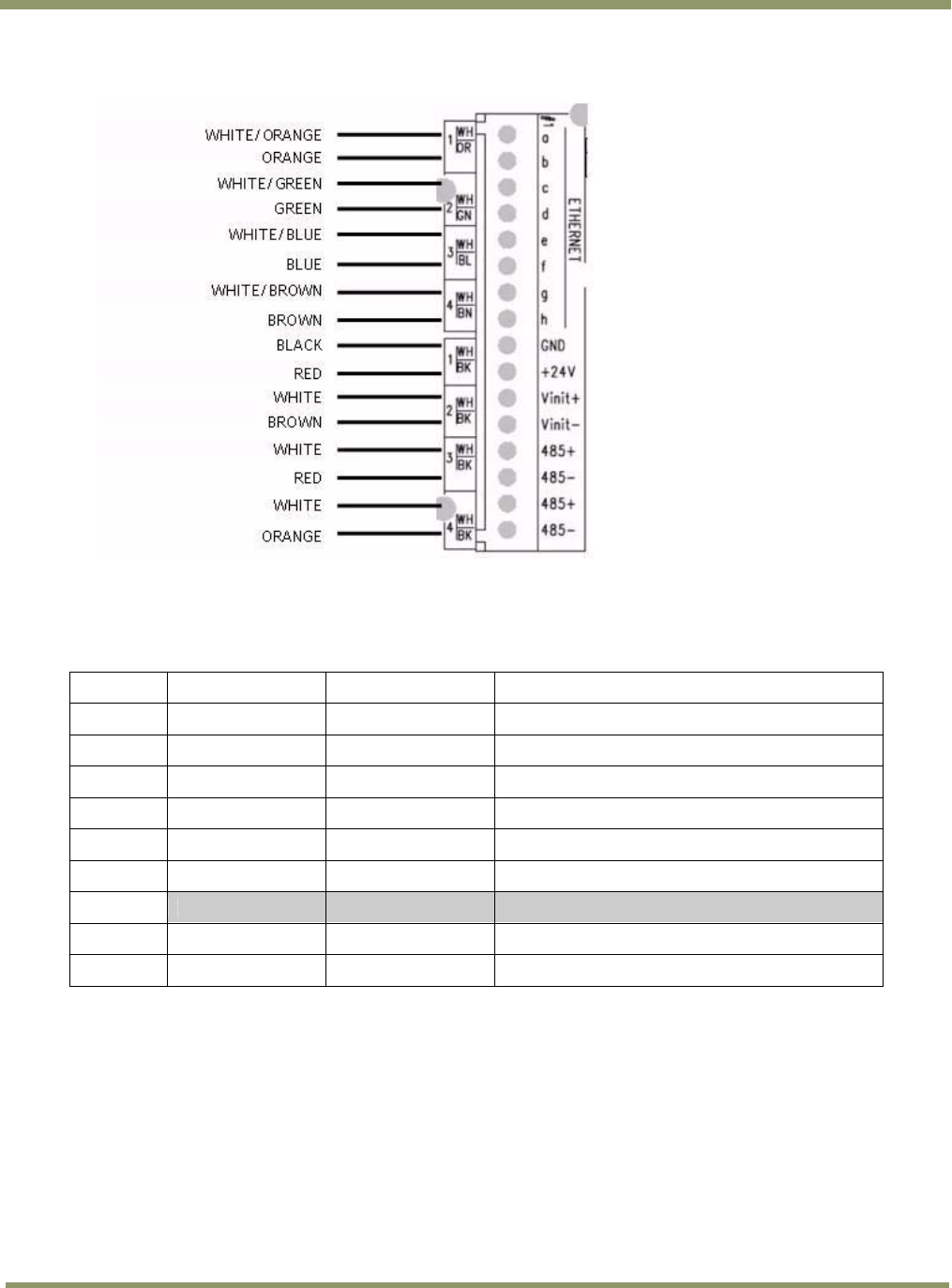
Figure 20. VIS CAM connections.
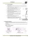
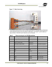
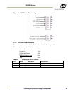
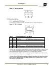
3.3.2 X3, X7 Traffic Light Sensor
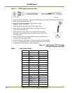
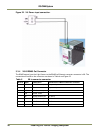
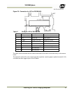
The Traffic Light Sensor TLS-300 connection to the J-Panel is shown in Table 4 and Figure 21.
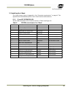
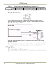
Table 4 TLS 300 to J-Panel connections.
X3 Pin X Signal Description
Connection to Light Sensor Cable wire color
1 +24V dc Power output
Yellow
2 Gnd Power return
White
3 D0+ RS485 databus D0+
White/orange
4 D0- RS485 databus D0-
Orange
5 D1+ RS485 databus D1+
White/brown
6 D1- RS485 databus D1-
Brown
X7 Pin X
1 Heater +24V dc Power output
Red/blue and Blue/red
2 Heater gnd Power return
White/green and Green