


VIS-CAM System
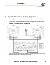
76 Appendix B: J-Panel Functional & Connector Description
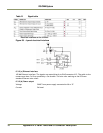
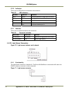
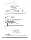
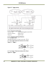
Figure 75. Principle in the power distribution.
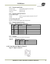
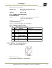
6.7.2 Connector specification
Connector type: 2 pole WAGO pluggable terminal block
Connector on board: WAGO 734-232
Cable part: WAGO 734-202
6.7.3 Connector signal specifications
24V DC power input. The two connectors are connected in parallel (unfused).
Maximum total current to X1, X2, X3 and X8: 6,3 A (fused value)
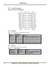
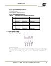
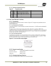
6.7.4 Connector physical Interface
Table 29 Physical connection for pins.
Pin Signal Description
Connection to
1 +24
V
+24V DC
24V DC power suppl
y
2 GND +24V return
24V DC power suppl
y
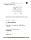
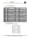
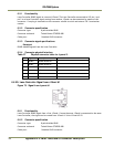
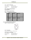
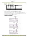
6.8 X8: RS485 signal to Ethernet interface
Figure 76. RS485 to Ethernet
6.8.1 Functionality
Interface to RS485-to-Ethernet converter. The signals come from the Light Sensor connection (X3).
Two power outputs for supplying the converter are available.