


Appendix B: J-Panel Functional & Connector Description 67
VIS-CAM System
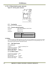
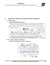
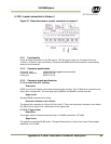
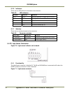
6.2.3 (c) Ethernet Interface
100 Mb Ethernet interface. The signals are routed directly to RJ45 connector X11. The cable to the
camera must be a Cat 5e or preferably a Cat 6 cable. The wire color marking on the PCB uses
standard Ethernet wire colors.
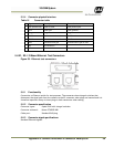
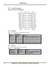
6.2.3 (d) Power output
Voltage 24VDC from power supply connected to X6 or X7
Current 2A fused
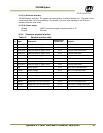
6.2.4 Connector physical Interface
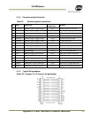
Table 18 Physical interface table
Pin Signal Description
Connection to
I/O Board X4
Remarks
1 Ethernet A+ Ethernet signal to gigabit switch
pin 1
Cat5e/6 cable white/orange
2 Ethernet A- Ethernet signal to gigabit switch
Pin 2
Cat5e/6 cable orange
3 Ethernet B+ Ethernet signal to gigabit switch
Pin 3
Cat5e/6 cable white/green
4 Ethernet B- Ethernet signal to gigabit switch
Pin 4
Cat5e/6 cable green
5 Ethernet C+ Ethernet signal to gigabit switch
Pin 5
Cat5e/6 cable white/blue
6 Ethernet C- Ethernet signal to gigabit switch
Pin 6
Cat5e/6 cable blue
7 Ethernet D+ Ethernet signal to gigabit switch
Pin 7
Cat5e/6 cable white/brown
8 Ethernet D- Ethernet signal to gigabit switch
Pin 8
Cat5e/6 cable brown
9 Gnd Power ground Pin 9
Black wire in Red/Black pai
r
10 +24V dc Supply voltage Pin 10
Red wire in Red/Black pai
r
11 Vinit + Balanced trigger pulse positive
Pin 11
White wire in Brown/White pai
r
12 Vinit - Balance tripper pulse negative
Pin 12
Brown wire in Brown/White pai
r
13 RS485D+ RS485 Data+ for Lane Controlle
r
Pin 13
White wire in Red/White pai
r
14 RS485D- RS485 Data- for Lane Controlle
r
Pin 14
Red wire in Red/White pai
r
15 RS485D= RS485 Data+ for Lane Controlle
r
Pin 15
White wire in Orange/White pai
r
16 RS485D- RS485 Data- for Lane Controlle
r
Pin 16
Orange wire in Orange/White pai
r