


VIS-CAM System
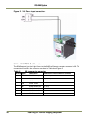
30 Installing the Vehicle Imaging Subsystem
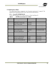
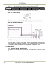
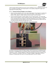
Table 10 Optimal Illumination Distance Between Camera and TNF
Distance in Feet
TS-9720EN
TSC-9720EN TS-2030EN
TSC-2030EN
TS-2076EN
TSC-2076EN
TS-1327EN
TSC-1327EN
3.5 TBD 2
1
TBD
TBD
TBD TBD
Distance measured from outer wall of Camera housing to outer wall of Flash unit.
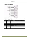
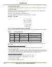
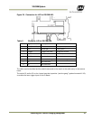
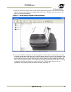
Figure 27. S3 switch setting
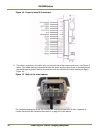
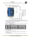
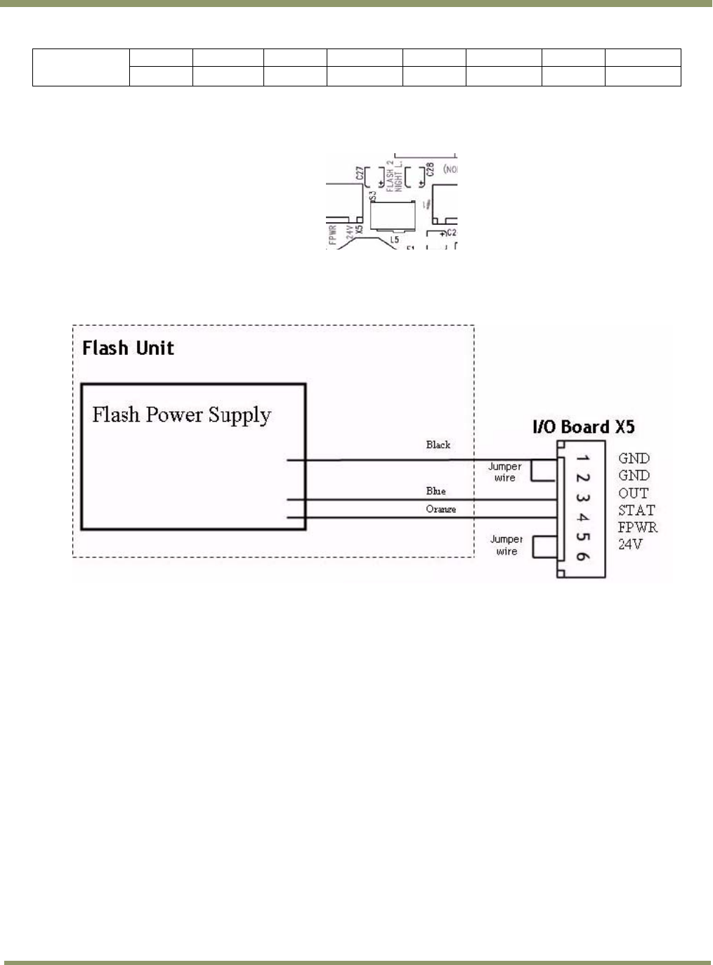
Figure 28 shows how to connect to an AC powered Flash unit with the I/O Board interface
electronics internally powered by the I/O Board. The Flash AC power connection is not shown.
Figure 28. Connecting an AC flash.
Other Flash connection examples are found in “ Appendix A: Camera Functional and Connector
Description” on page 43.
The VIS CAM 300 has an interface for two flashes. When this option is selected (S3 position “FLASH
2”) and the other flash is connected to connector X6, the two flashes fire alternately. Please refer
to “ Appendix B: J-Panel Functional and Connector Description” on page 67 for details.
3.5 Trigger Options
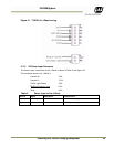
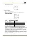
3.5.1 Installing The Laser Vehicle Detector
The connection from the Laser Vehicle Detector to the VIS CAM 300 is shown in Figure 29 and Table
10