


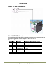
Installing the Vehicle Imaging Subsystem 21
VIS-CAM System
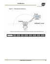
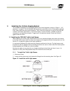
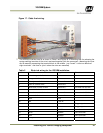
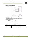
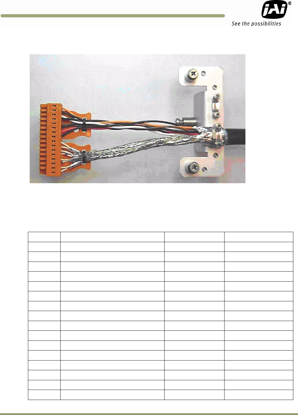
Figure 17. Cable final wiring.
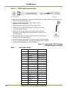
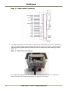
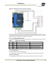
7. The wires are inserted into X4 as shown in Table 2 and Figure 18. A mounting tool for releasing the
spring enabling insertion of the wire is enclosed together with the connectors. (Mounting the wires
can be eased by separating the terminal block in the middle – just “break” it into two blocks of
eight terminals – and then re-join it when the wires are mounted)
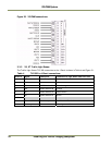
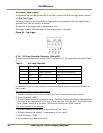
Table 2 Electrical wiring for the VIS CAM installation.
X4 Pin # Wire Color Signal
Remarks
1 White/orange in Cat5e/6 cable
Ethe
r
net A+
2 Orange in Cat5e/6 cable
Ethernet A-
3 White/green in Cat5e/6 cable
Ethernet B+
4 Green in Cat5e/6 cable
Ethernet B-
5 White/blue in Cat5e/6 cable
Ethernet C+
not used with VIS CAM
6 Blue in Cat5e/6 cable
Ethernet C-
not used with VIS CAM
7 White/brown in Cat5e/6 cable
Ethernet D+
not used with VIS CAM
8 Brown in Cat5e/6 cable
Ethernet D-
not used with VIS CAM
9 Black Gnd
10 Red +24V dc
11 Black Vinit+
Trigger signal
12 Pink Vinit-
Trigger signal
13 Black RS485D+
Lane Controlle
r
14 Brown RS485D-
Lane Controlle
r
15 Black RS485D+
Lane Controlle
r
16 Orange RS485D-
Lane Controlle
r