


Appendix B: J-Panel Functional & Connector Description 81
VIS-CAM System
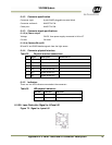
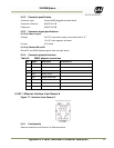
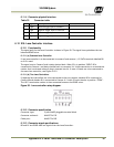
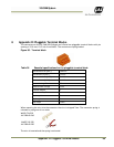
6.11.4 Connector physical Interface
Table 33 Connector table
Pin Signal Description
Connection to
1 Trig0+
Positive trigger input to camera 0
2 Trig0- Negative trigger input to camera
0
3 Trig1+
Positive trigger input to camera 1
4 Trig1- Negative trigger input to camera 1
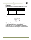
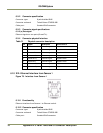
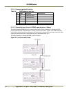
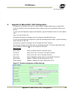
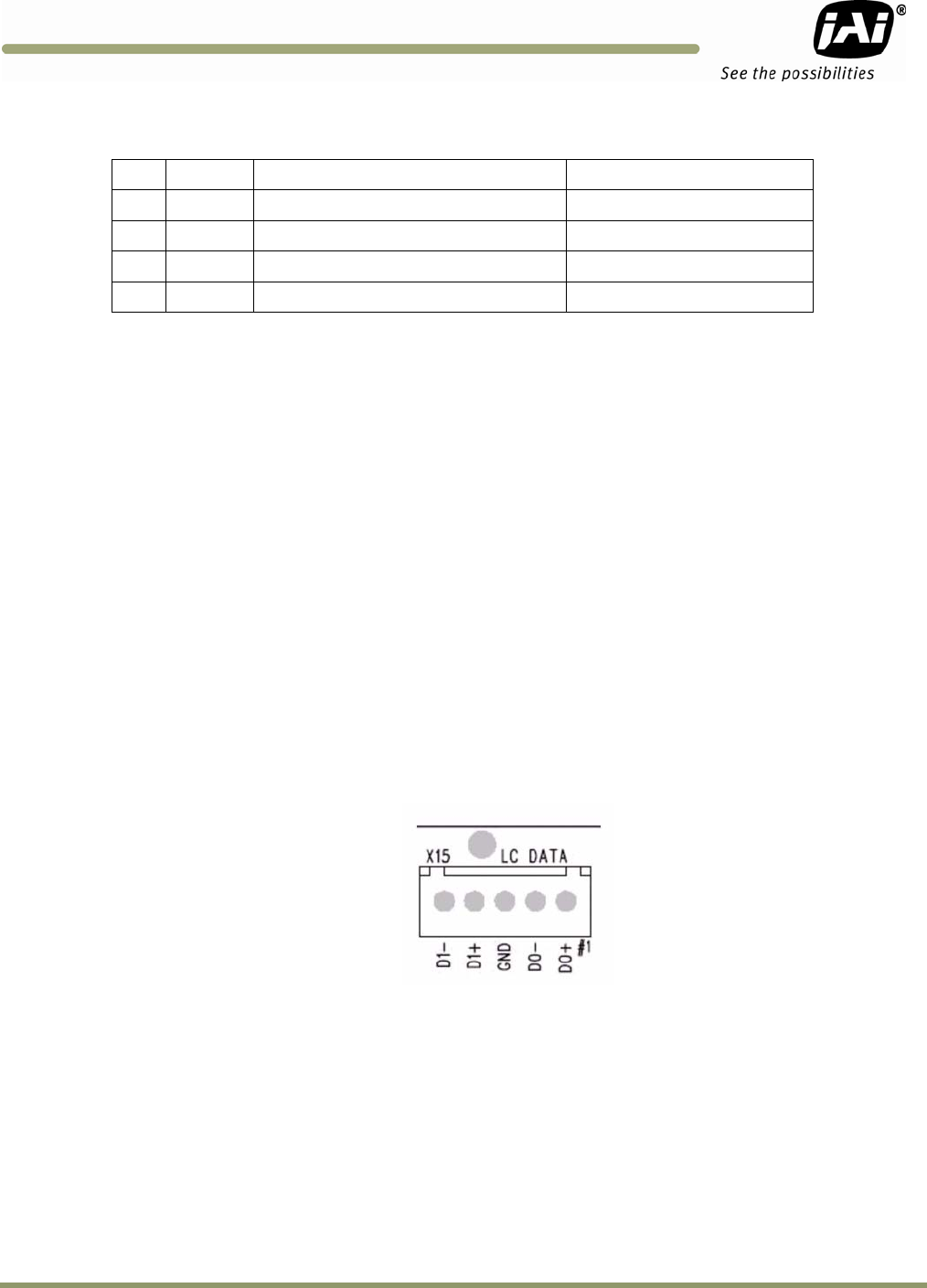
6.12 X15: Lane Controller interface
6.12.1 Functionality
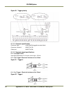
The signal path for the Lane Controller is shown in Figure 83. The signal lines symbolizes the two
balanced RS485 wires.
6.12.1 (a) Common Lane Controller
If one lane controller is to be connected to camera 0 and camera 1, LC DATA terminals labelled D0
on X15 is used.
The signal runs to Camera 0 and is daisy chained back. When S2 is in position “OPEN” D0 is
connected to Camera 1 and daisy chained back to connector X4. X4 has connection to a termination
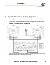
resistor that is activated when no plug is inserted into X4. If more J-Panels are to be connected to
the same lane controller, see Figure 6.12.5.
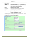
6.12.1 (b) Two Lane Controllers
If separate lane controllers are to be connected to the two cameras, databus D0 is connected to
Camera #0 and databus D1 is connected to Camera #1. Switch S2 must then be in position “TERM”.
The 120 ? termination resistor is then connected between the RS485 wires.
Figure 83. Lane controller setup diagram.
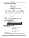
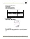
6.12.2 Connector specification
Connector type: 5 pole WAGO pluggable terminal block
Connector on board: WAGO 734-235
Cable part: WAGO 734-205
6.12.3 Connector signal specifications
D0 and D1 are RS485 data bus signals from the Lane Controller.