


Appendix A: Camera Functional & Connector Description 55
VIS-CAM System
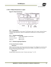
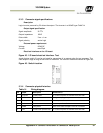
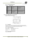
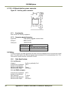
5.3.9 (a) Connector physical Interface
Table 15 Physical interface pinouts.
Pin Signal Description Connection to
1 Gnd Light/Flash Gnd Light/Flash ground (negative power terminal)
2 Out Light control/Strobe out Light control input or strobe input on flash unit
3 Stat Light/Strobe status Light/Flash Status output from unit
4 FPWR Light/Flash power Power from Light/Flash unit to output circuit on I/O Board
The Gnd signal on pin 1 is connected to the Gnd signal on X5 (pin 2) internally on the board.
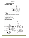
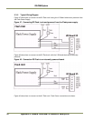
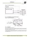
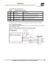
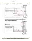
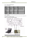
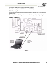
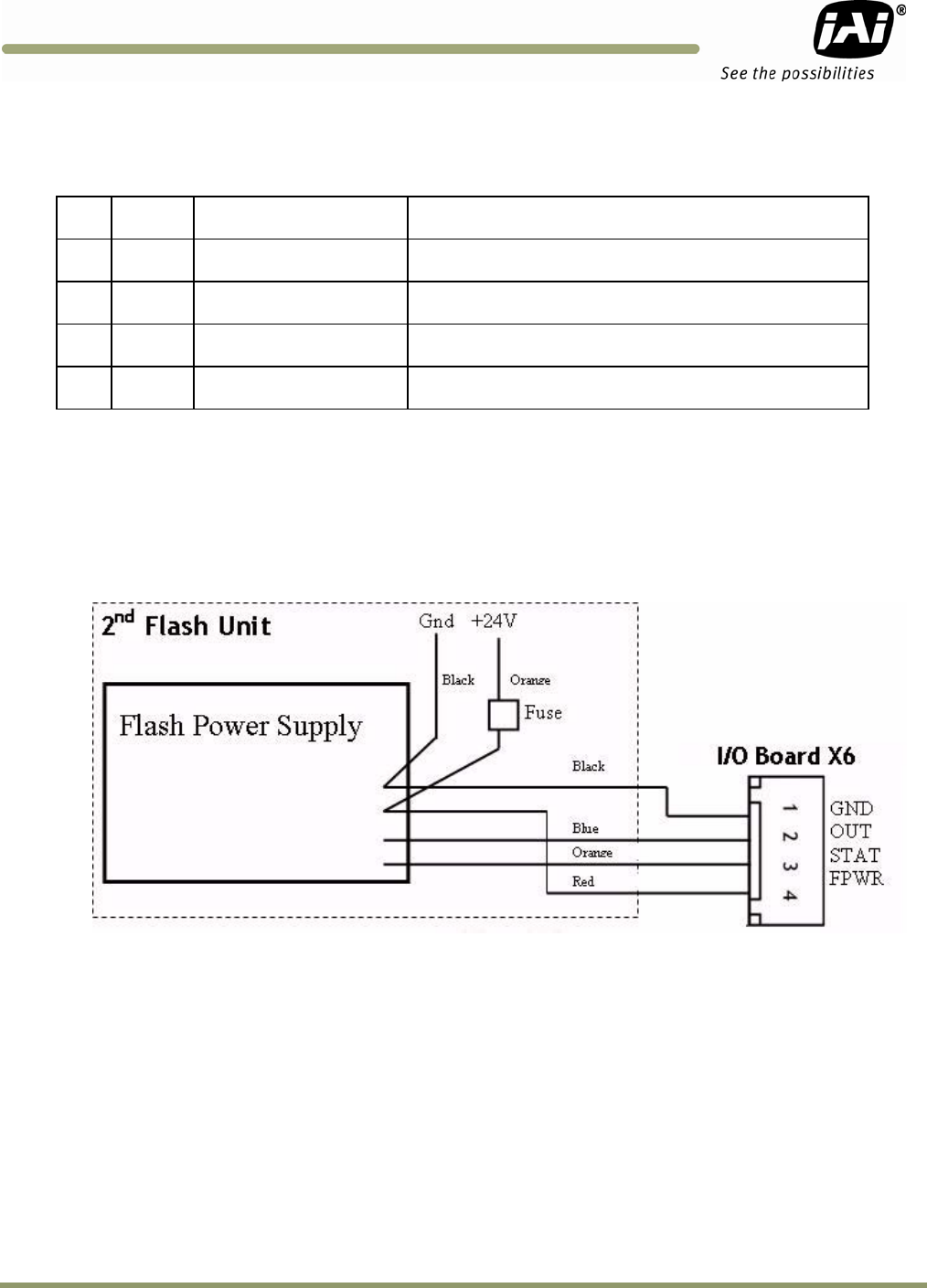
5.3.10 Typical Wiring Diagram
Figure 52 shows how to connect to the 2nd DC Flash unit having the I/O Board electronics powered
from the Flash Power Supply.
Figure 52. Wiring a second DC flash from the flash power supply.