


Installing the Vehicle Imaging Subsystem 31
VIS-CAM System
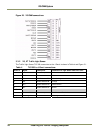
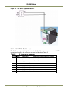
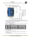
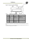
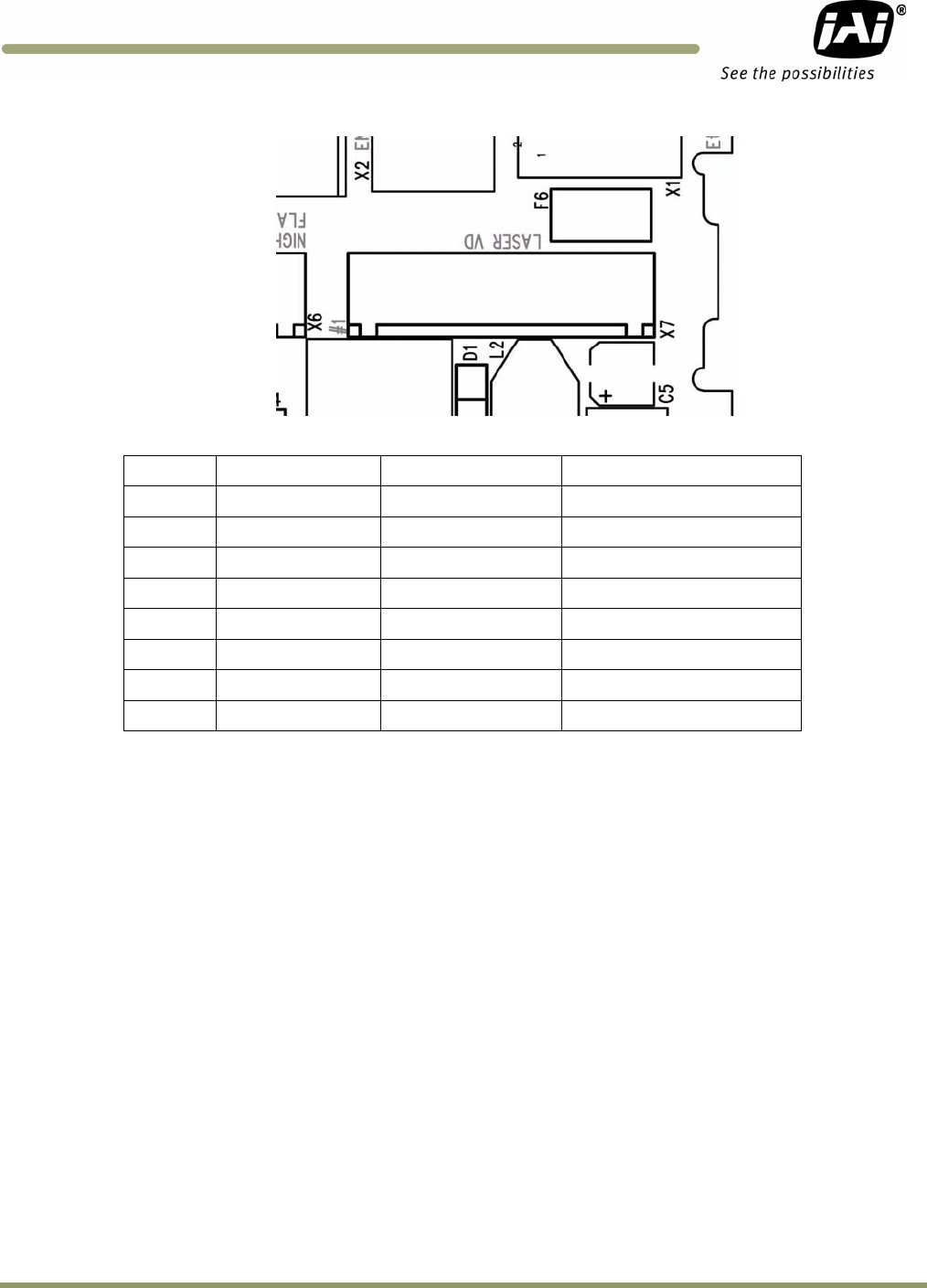
Figure 29. Connection for LVD to VIS CAM 400.
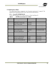
Table 11 Wiring for LVD to VIS CAM 400.
X7 Pin # Signal Description
Connection to
1 24V (Fused 0.5A)
Power to laser
Laser power input
2 Gnd Power gnd
Laser ground
3 Trigger Trigger from lase
r
Trigger out on lase
r
4 RS485- Transmit to lase
r
Receive input on lase
r
5 RS485+ Receive from lase
r
Transmit output on laser
6 Gnd Communication gnd
Communication gnd on laser
7 nc No connection -
-
8 nc No connection
-
The cable must be shielded and the shield connected to the metal at the cable entry in the camera
house.
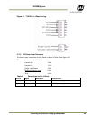
The switch S3 and/or S5 on the J-panel must be in position “positive going” (pushed towards X1/X2)
to enable the laser trigger input on the IO Board.