


VIS-CAM System
22 Installing the Vehicle Imaging Subsystem
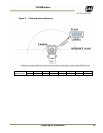
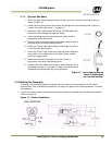
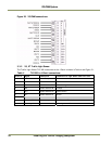
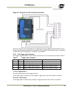
Figure 18. Properly wired X-4 connector.
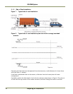
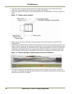
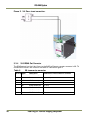
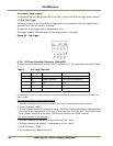
8. The cable is mounted in the cable entry on the back side of the camera as shown in the Figure 19
below. The rubber bushing is mounted around the jacket and the metal brace is mounted around
the shield securing proper electrical connection from the shield to the metal housing (se figure
Figure 19).
Figure 19. Back of the video camera.
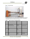
For a detailed description of the VIS CAM 300/400 interface please refer to See “ Appendix A:
Camera Functional and Connector Description” on page 43 in this manual.