


Table of Contents v
VIS-CAM System
Table of Contents
1
Introduction ............................................................................................. 1
1.1 Document Overview ................................................................................... 1
1.2 Product overview ...................................................................................... 1
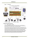
1.3 System Components description ..................................................................... 2
1.3.1 Traffic Light Sensor – TLS300 ........................................................................ 2
1.3.2 VISCAM ................................................................................................... 3
1.3.3 Illumination ............................................................................................. 4
1.3.4 VJP-300 Junction Panel. .............................................................................. 4
1.3.5 RS485 Device Server. .................................................................................. 4
1.3.6 ENSetup Program. ..................................................................................... 4
1.4 Operational Overview. ................................................................................ 4
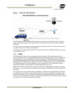
1.4.1 Trigger Mode ............................................................................................ 4
2 Preparing for installation ............................................................................. 5
2.1 Installation Preparation ............................................................................... 5
2.1.1 Over Lane Positioning ................................................................................. 5
2.1.2 Side of Road Installation ............................................................................. 14
3 Installing the Vehicle Imaging System ............................................................. 17
3.1 Installing the TNF-300 Traffic Light Sensor. ...................................................... 17
3.1.1 To install the Traffic Light Sensor: ................................................................. 17
3.1.2 Optional Side Mount .................................................................................. 19
3.2 Installing the Camera(s) ............................................................................. 19
3.3 Installing the J-Panel ................................................................................. 23
3.3.1 X1 and X2 VIS CAM 300/400 ......................................................................... 23
3.3.2 X3, X7 Traffic Light Sensor .......................................................................... 24
3.3.3 X6 Power Input Connector ........................................................................... 25
3.3.4 X8 LS RS485 Out Connector ......................................................................... 26
3.3.5 X14 Trigger Input Connector ........................................................................ 27
3.3.6 X15 Lane Controller Connector (X4 and X5) ...................................................... 28
3.4 Illumination Options .................................................................................. 29
3.4.1 Installing the TNF-31 Flash .......................................................................... 29
3.5 Trigger Options ........................................................................................ 30
3.5.1 Installing The Laser Vehicle Detector ............................................................. 30
4 System Set-Up ......................................................................................... 33
4.1 Preparation for Alignment ........................................................................... 33
4.1.1 Pre-Alignment Checklist ............................................................................. 33
4.1.2 Select a Suitable Vehicle, License Plate, and Plate Stand for the Setup .................... 34
4.1.3 Select the Camera to Align .......................................................................... 34
4.1.4 Validate the Installation Geometry ................................................................ 34
4.1.5 Edit the alignment settings on the Setup Computer ............................................ 34
4.1.6 Connect the Setup Computer to the Camera ..................................................... 35
4.1.7 Drive and Park the Setup Vehicle Correctly ...................................................... 36
4.1.8 Properly Position the License Plate Stand ........................................................ 36
4.1.9 Perform Initial Lens Adjustment and Camera Aiming ........................................... 36
4.1.10 Finalize Lens Adjustments and Camera Aiming ................................................ 39
4.1.11 Flash Head Alignment .............................................................................. 42
5 Appendix A: Camera Functional and Connector Description ................................... 45
5.1 I/O Board Layout ...................................................................................... 46
5.2 X4: I/O Board Connection to J-panel .............................................................. 47
5.2.1 Functionality ........................................................................................... 47
5.2.2 Connector specification .............................................................................. 47