


VIS-CAM System
66 Appendix B: J-Panel Functional & Connector Description
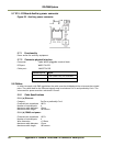
6.2.1 Functionality
Power and data connection to the EN camera. The 24V power supply for all camera functions
(Camera, I/O Board, light and heaters), Ethernet and RS485 data communication is connected by
means of this connector.
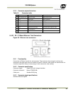
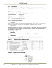
6.2.2 Connector specification
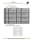
Connector type: 16 pole WAGO pluggable terminal block
Connector on board: WAGO 734-246
Cable part: WAGO 734-216
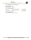
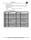
6.2.3 Connector signal specifications
6.2.3 (a) Lane Controller interface
Description
RS485 two wire half-duplex multi-drop communication network. The I/O Board has connections for
daisy chain configuration. The two signal pairs (RS485D+ and RS485D-) can be reversed.
Signal levels:
Standard RS485 communication levels. Electrical interface on the J-Panel: The signals are connected
to J-Panel X15 pin 1 and 2. There are termination resistors on the board. See Figure 49 on page 53
for a description of the signal path.
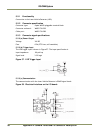
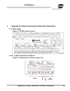
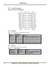
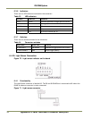
6.2.3 (b) Trigger output
Description
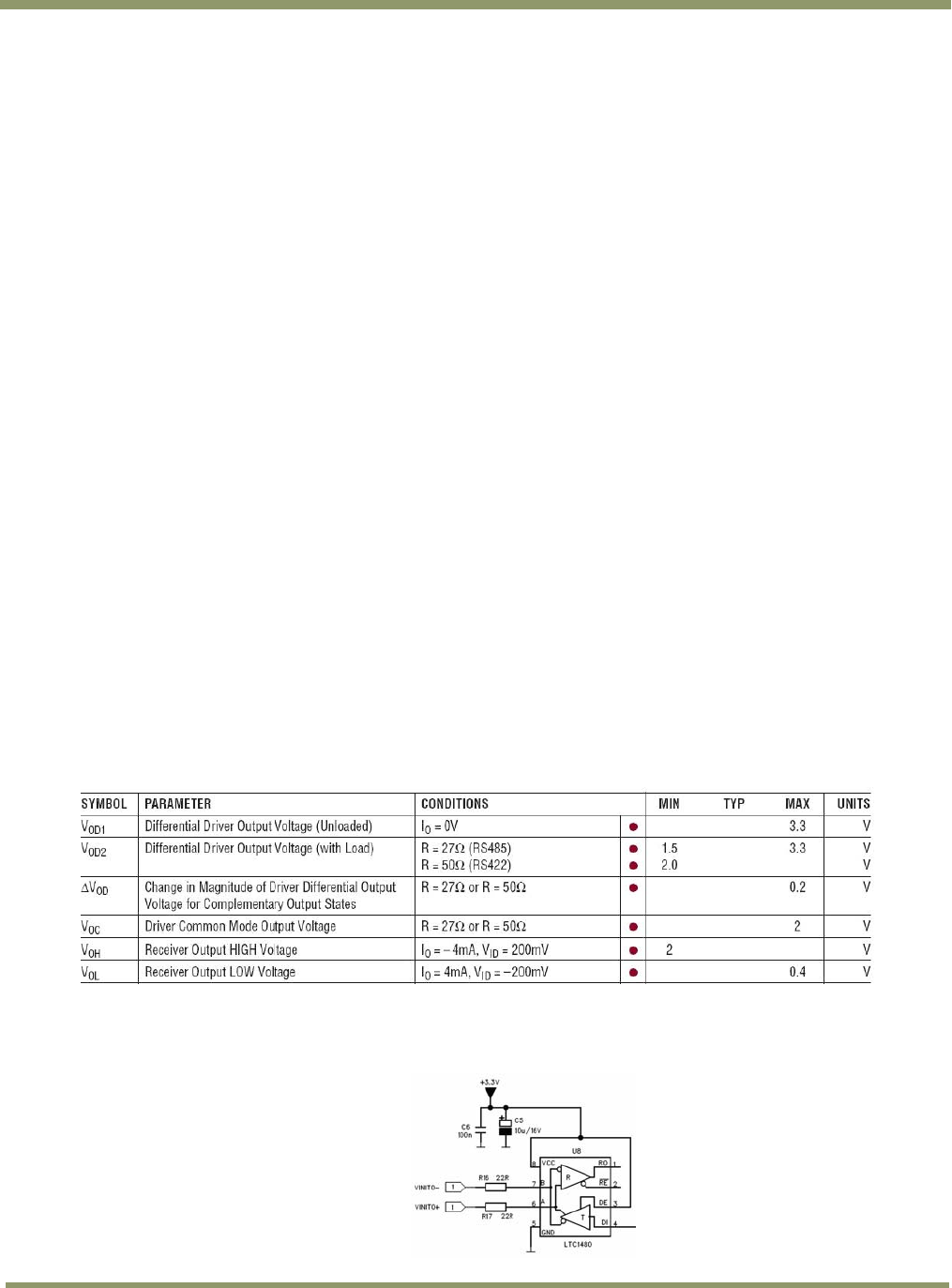
The trigger output is balanced and the driver is a RS485 transmitter (LTC1480).
Signal levels
The signal levels are at standard RS485 levels. The specification below is taken from Linear
Technologies datasheet for LTC1480:
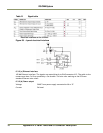
Table 17 Signal parameters and conditions.
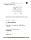
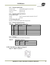
Electrical interface on the J-Panel:
Figure 65. J-Panel electrical interface