


Appendix A: Camera Functional & Connector Description 59
VIS-CAM System
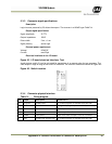
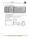
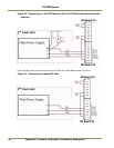
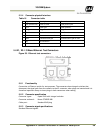
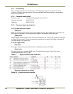
5.5.4 Connector physical Interface
Table 16 Connector table
Pin Signal Description
Connection to
1 24V (Fused 0.5A) Power to laser
Laser power input
2 Tnd Power gnd
Laser groundd
3 Trigger
Trigger from lase
r
Trigger out on lase
r
4 RS485- Communication interface
RS-485-
on lase
r
5 RS485+
Communication interface
RS-485+ on lase
r
6 Gnd Communication gnd
Communication gnd on laser
7 NC No connection
--
8 NC No connection
--
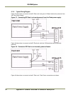
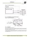
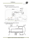
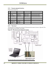
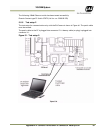
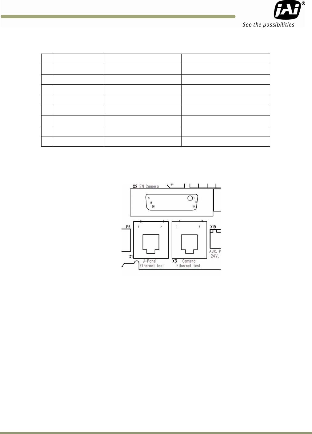
5.6 X1, X3: I/O Board Ethernet Test Connectors
Figure 59. Ethernet test connectors.
5.6.1 Functionality
Connection to Ethernet switch for test purposes. The connectors have integral switches that
disconnect the signal path from the camera to the X2 connector when plugs are inserted and it is
therefore important always to insert plugs in both connectors when testing.
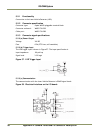
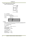
5.6.2 Connector specification
Connector types: 8 pole RJ45 with integral switches
Connector on board: Kinsun ST3009F-880
Cable part: Standard RJ45 plug
5.6.3 Connector signal specifications
Standard Ethernet signals.