


System Set-Up 37
VIS-CAM System
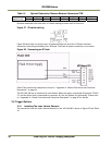
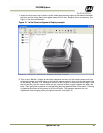
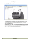
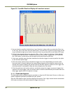
7. Adjust the lens zoom ring to obtain a plate width approximately equal to the distance between
the short vertical sizing marks that appear above the tilt line. Readjust focus as necessary. See
Figure 31 for more information.
Figure 31. Initial Camera Alignment Display example.
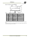
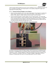
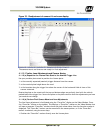
8. Turn on the “Roll Bar” display on the Setup computer and then roll the camera mount until the
horizontal bumper and trunk seams on the vehicle appear perfectly level with the horizontal line
of the display. Use one 7/16" closed-end wrench on the roll gear to fine-tune the roll angle. Hold
the roll position with the wrench while you use a second wrench to gently tighten the other roll
bolts. Then apply both wrenches to corresponding bolts on opposite sides of the mount. Twisting
in opposite directions to fully secure all of the roll bolts. This approach prevents the roll
adjustment from changing while you tighten the bolts. See Figure 32.