


Installing the Vehicle Imaging Subsystem 29
VIS-CAM System
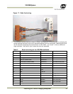
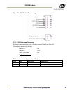
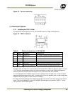
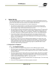
Figure 25. Two lane controller.
3.4 Illumination Options
3.4.1 Installing the TNF-31 Flash
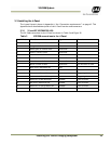
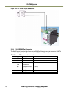
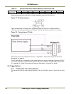
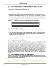
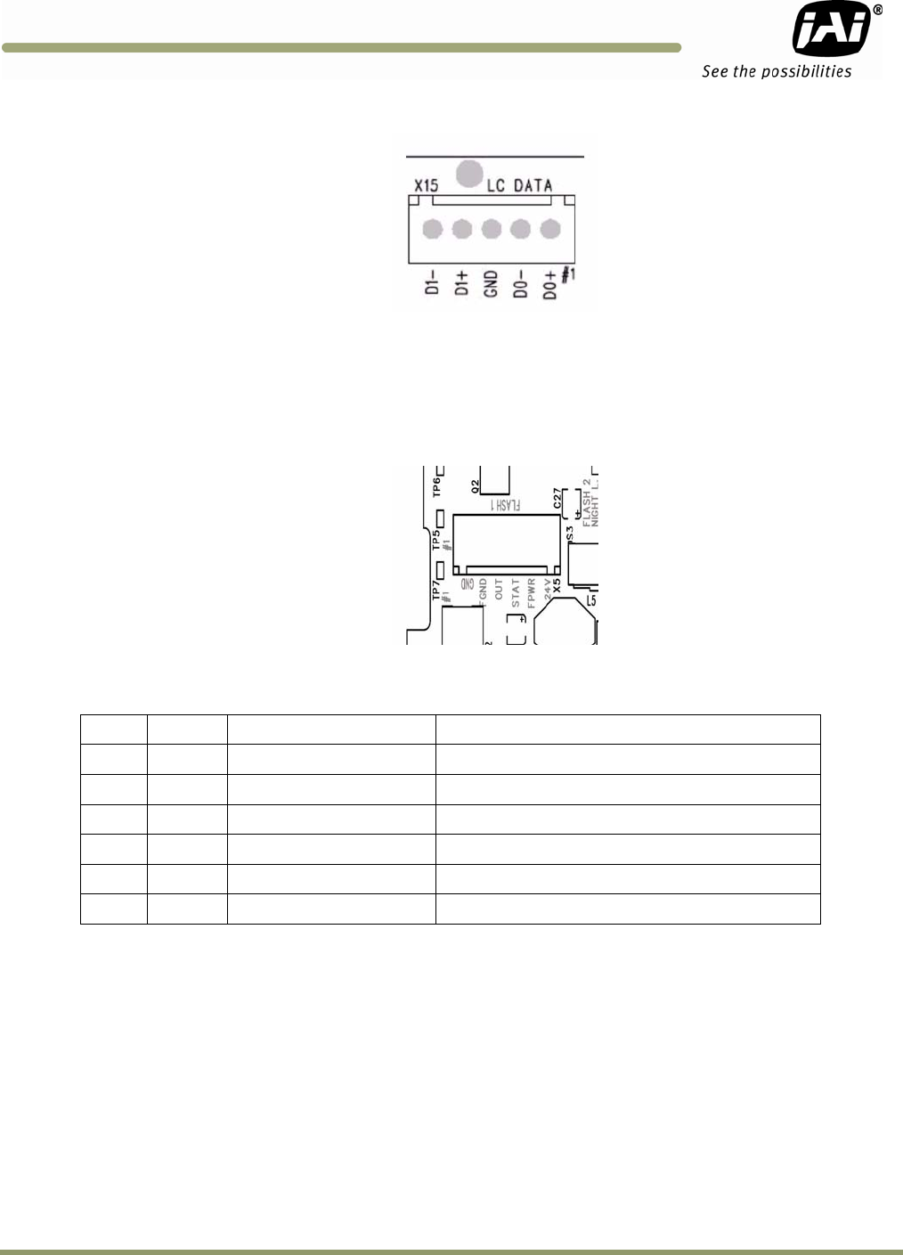
The connection to the Flash unit in the VIS CAM 300 is shown in Table 9 and Figure 26.
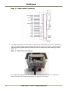
Figure 26. TNF-31 flash unit
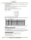
Table 9 Flash unit connection in VIS CAM 400.
Pin Signal Description Connection to
1 I/O Gnd IO Board Gnd
Pin 2 when no power is available from the flash
2 Gnd Flash Gnd Flash ground (negative power terminal)
3 Out Strobe out Strobe input on flash unit
4 Stat Strobe status
Status output from flash unit
5 FPW
R
Flash powe
r
Power from flash to output circuit on I/O Board
6 24
V
IO board 24V (Fused0.5A)
Pin 5 when no power is available from the flash
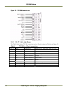
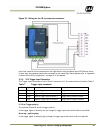
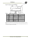
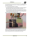
The cable from the flash unit is connected to the VIS CAM 300 I/O Board as shown in figure 3.17 and
3.18. There are two examples shown: one where the output circuit on the I/O Board is powered
from the flash unit and one where the output circuit is powered from the I/O Board.
It is recommended that I/O Board output circuit be powered from the flash unit in order to obtain
galvanic isolation between the to units. In cases where this is not possible (such as when using mains
supplied flash units) power is taken from the I/O Board.
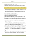
The cable must be shielded and the shield connected to the metal at the cable entry in the camera
house. The switch labelled S3 on the VIS CAM 300 I/O Board must be in position “NIGHT L” (away
from connector X5 as shown below).