


VIS-CAM System
70 Appendix B: J-Panel Functional & Connector Description
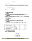
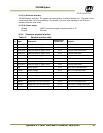
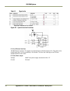
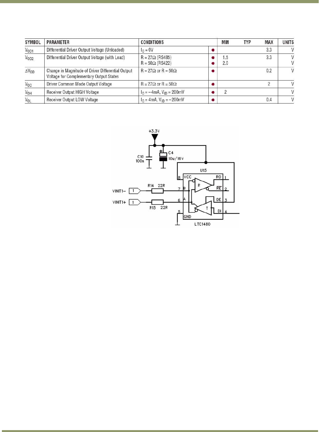
Table 21 Signal table
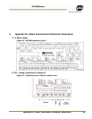
Electrical interface on the J-Panel:
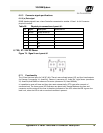
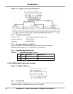
Figure 68. J-panel electrical interface
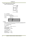
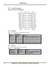
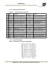
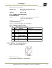
6.3.3 (c) Ethernet Interface
100 Mb Ethernet interface. The signals are routed directly to RJ45 connector X12. The cable to the
camera must be a Cat 5e or preferably a Cat 6 cable. The wire color marking on the PCB uses
standard Ethernet wire colors.
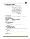
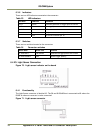
6.3.3 (d) Power output
Voltage: 24VDC from power supply connected to X6 or X7
Current: 2A fused