


Installing the Vehicle Imaging Subsystem 19
VIS-CAM System
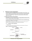
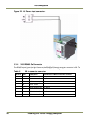
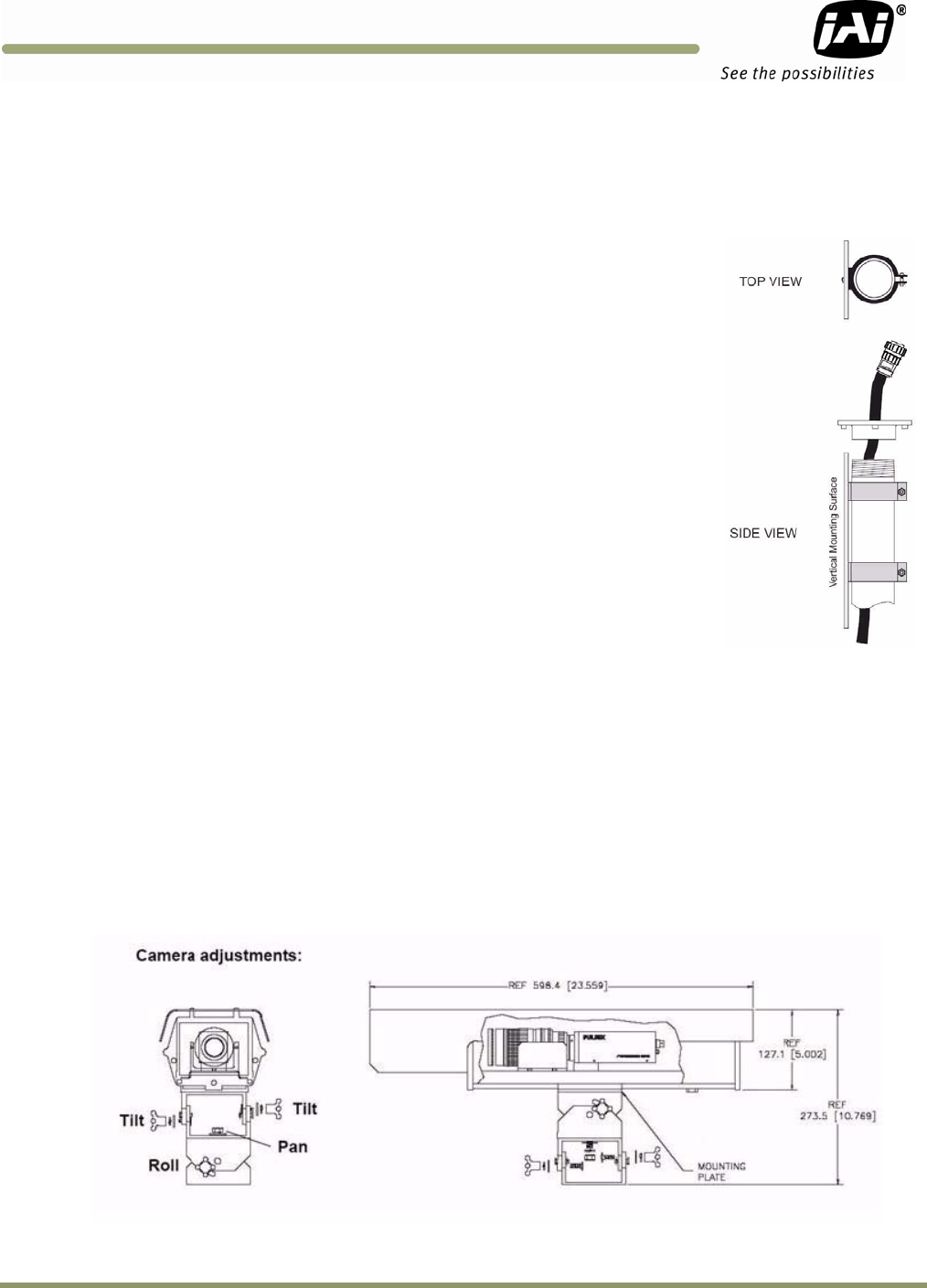
3.1.2 Optional Side Mount
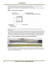
1. Attach the pipe clamps approximately 6-inches apart on a vertical mounting surface as
shown in Figure 13.
2. Loosen the four Allen screws and remove the flange from the mounting base. Figure 10,
“Install the traffic light sensor.,” on page 15.
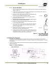
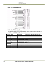
3. Route the Traffic Light Sensor end of the TLS-300 signal and
the power cable through the pipe and flange.
4. Screw the flange onto the pipe somewhat tightly to allow
subsequent minor adjustment
5. Place the pipe in the pipe clamps and tighten them to secure
the pipe to the vertical mounting surface.
6. Attach the Traffic Light Sensor body to the flange and secure
it with the four Allen screws.
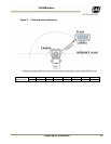
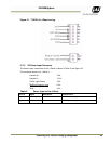
7. Orient the Traffic Light Sensor such that the white reflectors
are parallel to the trigger plane with side B facing (visible
from) the trigger plane
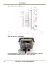
8. Route the free end of the cable to the VIS J-Panel in
accordance with local code requirements
9. Connect the color-coded wires to the J-Panel connector X3 as
described in Section 3.3 on page 21. Make sure that no power
is applied when performing any wiring operation.
Figure 13. Pipe clamps should be
about 6-inches apart
on a vertical surface.
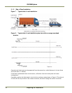
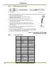
3.2 Installing the Camera(s)
In general, the camera(s) should be aimed at the most likely cross-lane position of the vehicle
license plates. See “Installation Preparation” on page 6 for general site layout guidelines. To install
the camera(s):
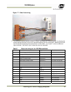
1. Attach the camera mount to the camera enclosure using the included mounting bolts and washers.
Refer to Figure 14.
Figure 14. Camera Installation