


VIS-CAM System
18 Installing the Vehicle Imaging Subsystem
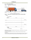
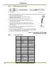
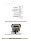
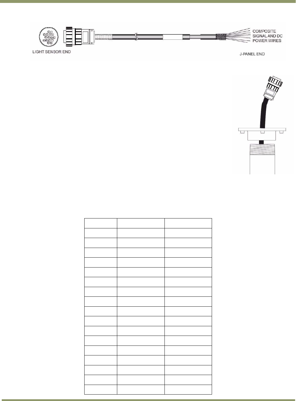
Figure 11. TLS-300 signal and power cable.
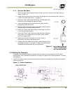
3. Route the Traffic Light Sensor end of the TLS-300 signal and power cable through the mounting
pipe and the flange (see Figure 12)
4. Screw the flange onto the pipe, finger-tight, to allow
subsequent minor adjustment
5. Attach the cable connector to the Traffic Light Sensor
6. Attach the Traffic Light Sensor body to the flange and secure
it with the four Allen screws
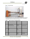
7. Orient the Traffic Light Sensor such that the white reflectors
are parallel to the trigger plane with side B facing (visible from)
the trigger plane
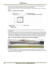
8. Route the free end of the cable to the VIS J-Panel in accordance
with the local code requirements
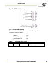
9. Connect the color-coded wires to J-Panel connector X3 as described
in “X3, X7 Traffic Light Sensor ” on page 22. Make sure that no power
is applied when performing any wiring operation.
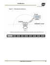
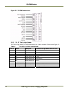
Figure 12. Installing the TLS-300 through
the mounting pipe and flange.
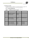
Table 1 Light Sensor Cables
PIN# Wire color
Signal
1 White/green
Heater gnd
2 Green
Heater gnd
3 Red/blue
Heater +24V dc
4 Blue/red
Heater +24V dc
5 -
nc
6 Yellow
+24V dc
7 -
nc
8 -
nc
9 -
nc
10 White
Gnd
11 -
nc
12 -
nc
13 Brown
D1-
14 White/brown
D1+
15 Orange
D0-
16 White/orange
D0+
- Black
Shlds