


VIS-CAM System
82 Appendix B: J-Panel Functional & Connector Description
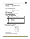
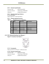
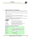
6.12.4 Connector physical Interface
Table 34 WAGO physical interface
Pin Signal Description
Connection to
1 D0+ RS485 databus D0+
2 D0- RS485 databus D0-
3 Gnd
4 D1+ RS485 databus D1+
5 D1- RS485 databus D1-
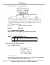
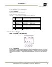
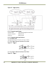
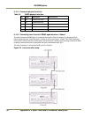
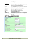
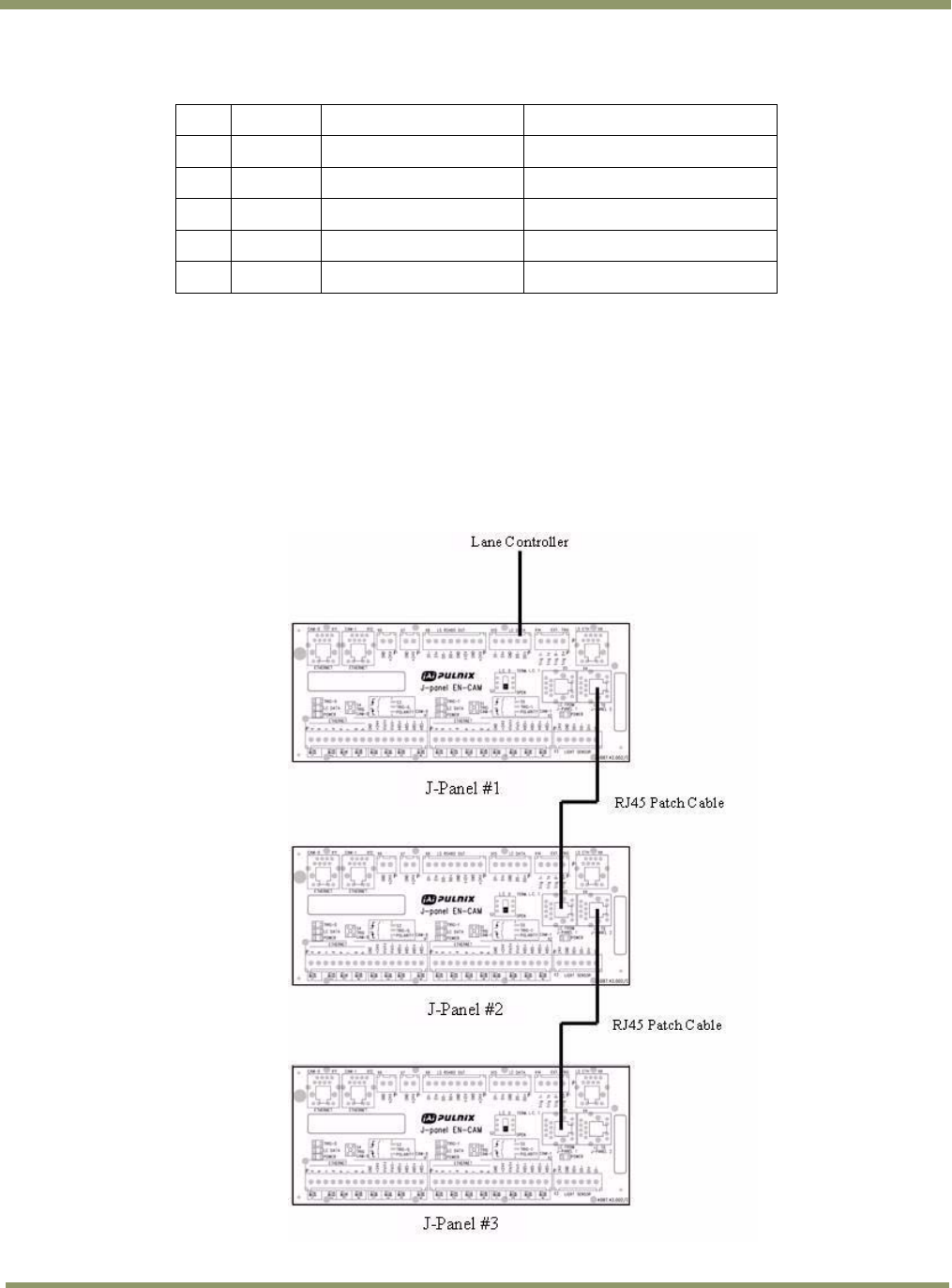
6.12.5 Connecting Lane Controller RS485 signal between J-Panels
The Lane Controller RS485 signal is connected from one J-Panel to another by connecting RJ45
Patch cables between X4 on the source J-Panel to X5 on the receive J-Panel. The RJ45 connectors
have build-in switch function to disconnect the termination resistor when the plug is inserted. When
no plug is inserted into the X4 connector the line is terminated with 120 ?.
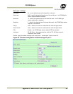
The Lane Controller is connected to D0 on X15 J-Panel #1.
Figure 84. Lane controller setup.