


Appendix B: J-Panel Functional & Connector Description 73
VIS-CAM System
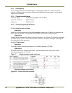
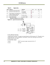
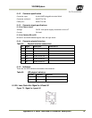
6.4.2 Connector specification
Connector type: 6 pole WAGO pluggable terminal block
Connector on board: WAGO 734-236
Cable part: WAGO 734-206
6.4.3 Connector signal specifications
6.4.3 (a) Power output
Voltage: 24V DC from power supply connected to X6 or X7
Current: 2A fused
6.4.3 (b) Databus D0 and D1
D0 and D1 are RS485 databus signals from the light sensor.
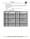
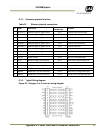
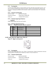
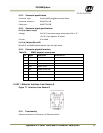
6.4.4 Connector physical Interface
Table 25 Physical interface connections
Pin Signal Description
Connection to
1 24V dc Power output
2 Gnd Power return
3 D0+ RS485 databus D0+
4 D0- RS485 databus D0-
5 D1+ RS485 databus D1+
6 D1- RS485 databus D1+
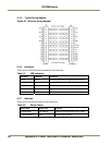
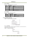
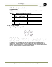
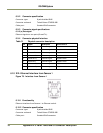
6.4.5 Indicators
There are two LED indicators mounted at the connector:
Table 26 LED physical indicators
LED label LED color
Indication
Powe
r
Green
24V present at connector 1
red
No 24V at connector pin 1
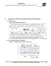
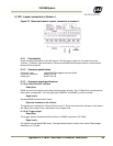
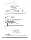
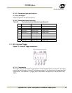
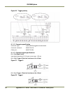
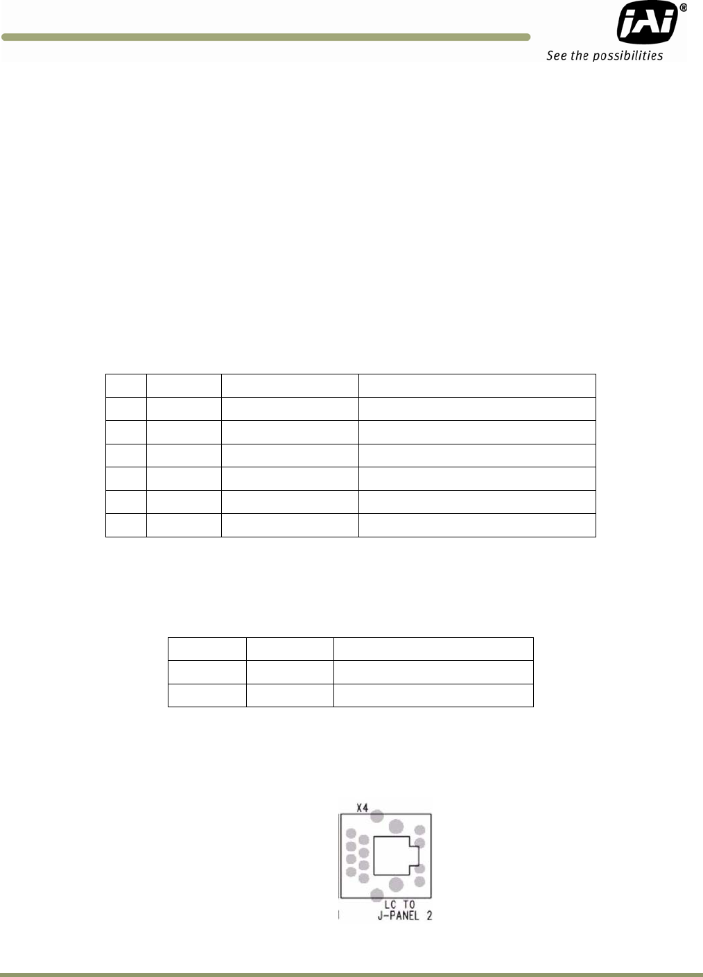
6.5 X4: Lane Controller Signal to J-Panel #2
Figure 72. Signal to J-panel #2