


Appendix A: Camera Functional & Connector Description 49
VIS-CAM System
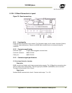
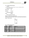
5.2.4 (a) Ethernet Interface
Description: 100 Mb Ethernet interface. The signal must be connected to a gigabit Ethernet switch
for best performance. The cable must be a Cat 5e or preferably a Cat 6 cable. The wire color
marking on the PCB is standard Ethernet wire colors.
5.2.4 (b) Power input
Voltage 24VDC±20%
Current 0.3A with heaters and LED light off
Max current inrush app 2.5A
Heaters on 1.3A totally
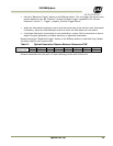
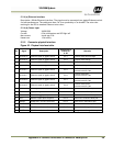
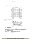
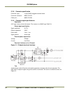
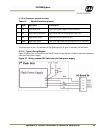
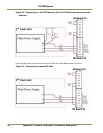
5.2.5 Connector physical Interface
Figure 42. Physical interface table.
Pin Signal Description
Connection to
J-Panel X1
or X2
Remarks
1 Ethernet A+ Ethernet signal to gigabit switch
pin 1
Cat5e/6 cable white/orange
2 Ethernet A- Ethernet signal to gigabit switch
Pin 2
Cat5e/6 cable orange
3 Ethernet B+ Ethernet signal to gigabit switch
Pin 3
Cat5e/6 cable white/green
4 Ethernet B- Ethernet signal to gigabit switch
Pin 4
Cat5e/6 cable green
5 Ethernet C+ Ethernet signal to gigabit switch Pin 5
Cat5e/6 cable white/blue
not used with VIS CAM
6 Ethernet C- Ethernet signal to gigabit switch Pin 6
Cat5e/6 cable blue
not used with VIS CAM
7 Ethernet D+ Ethernet signal to gigabit switch Pin 7
Cat5e/6 cable white/brown
not used with VIS CAM
8 Ethernet D- Ethernet signal to gigabit switch Pin 8
Cat5e/6 cable brown
not used with VIS CAM
9 Gnd Power ground Pin 9
Black wire in Red/Black pai
r
10 +24V dc Supply voltage Pin 10
Red wire in Red/Black pai
r
11 Vinit + Balanced trigger pulse positive
Pin 11
White wire in Brown/White pai
r
12 Vinit - Balance t
r
ipper pulse negative
Pin 12
Brown wire in Brown/White pai
r
13 RS485D+ RS485 Data+ for Lane Controlle
r
Pin 13
White wire in Red/White pai
r
14 RS485D- RS485 Data- for Lane Controlle
r
Pin 14
Red wire in Red/White pai
r
15 RS485D= RS485 Data+ for Lane Controlle
r
Pin 15
White wire in Orange/White pai
r
16 RS485D- RS485 Data- for Lane Controlle
r
Pin 16
Orange wire in Orange/White pai
r